Swap Adapters and Offset Delay Calibration Methods
The Swap Adapters or Offset Delay calibration method is used when you
do NOT have calibration standards with the same connector type as your
DUT. In this case, the Offset Delay is the preferred calibration method
over the Swap Adapters method.
The Swap Adapters calibration method (also known as Swap Equal Adapters
and Equal Length Adapters) was used in the past as a quick alternative
to the more tedious adapter
removal method. This method requires that the adapters be of equal
electrical length. There are two adapters for each port. The swap equal
adapter method implicitly assumes the adapters have identical return loss.
The finite return loss of each adapter on each port degrades both the
residual directivity and residual match terms. The offset delay calibration
only has one adapter. The return loss of this one adapter will degrade
the residual directivity and residual match error terms.
Note: For
any other reason, these calibration methods are NOT
recommended because the Unknown
Thru method is more convenient AND more accurate.
The Offset Delay calibration method uses the available standards for
calibration then adds offset delay to the measurement plane to account
for each adapter used. This eliminates the need for adapters with equal
electrical length and is preferred over the Swap Adapters method.
Swap
Adapters Procedure
The following is an example procedure showing how to perform a Swap
Adapters 2-port calibration for a non-insertable DUT. The DUT has 2.92
mm connectors. You do NOT have 2.92 mm calibration standards, but you
DO have 2.4 mm standards and adapters that have the same electrical delay
as the 2.92 mm adapters.
Adapters A1 and A2 = test port to 2.4 mm adapters
Adapters B1 and B2 = test port to 2.92 mm adapters
Start the Cal Wizard and select Guided (Smart)
Cal. Note: The
VNA will NOT prompt you to connect the adapters by name or
when to swap the adapters. |
Specify the connector type and gender and
Cal Kit of the adapter that you will be using (2.4 mm) - NOT
the connector type of the DUT (2.92 mm). By specifying the
connector gender, you are also specifying the Thru method
(flush thru for insertable and Unknown Thru for non-insertable.)
For example, when both DUT ports have female connectors, we
will perform an Unknown Thru cal. |
When prompted for reflection standards on
port 1, connect the Open, Short, and Load standards to Adapter
A1. When prompted for reflection standards on
port 2, connect the Open, Short, and Load standards to Adapter
A2. |
|
When prompted for a Thru connection, swap
Adapter A1 and A2 for B1 and B2. Connect the Thru device.
This could be any device that meets the requirements of the
Unknown
Thru standard. In the case of a non-insertable DUT, connect
B1 and B2. |
|
Make DUT measurements with Adapters B1 and
B2 in place. |
|
Offset
Delay Procedure
The following is an example procedure showing how to perform a 2-port
calibration for a non-insertable DUT using Offset Delay to account for
the added delay of two adapters. The DUT has 2.92 mm connectors. You do
NOT have 2.92 mm calibration standards, but you DO have 2.4 mm standards
and adapters.
Adapters = test port to 2.4 mm (female)-to-2.92 mm (male) adapters
Start the Cal Wizard and select Guided (Smart)
Cal. |
Specify the connector type and gender and
Cal Kit that you will be using (2.4 mm) - NOT the connector
type of the DUT (2.92 mm). By specifying the connector gender,
you are also specifying the Thru method (flush thru for insertable
and Unknown Thru for non-insertable.) For example, when both
DUT ports have female connectors, we will perform an Unknown
Thru cal. |
When prompted for reflection standards on
port 1, connect the Open, Short, and Load standards. When prompted for reflection standards on
port 2, connect the Open, Short, and Load standards. |
|
When prompted for a Thru connection, connect
the Thru device between port 1 and port 2. This could be any
device that meets the requirements of the Unknown
Thru standard. In this example of a non-insertable DUT,
a female-to-female 2.4 mm barrel adapter is used as the Thru
device. |
|
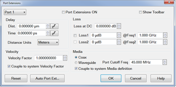
Click on Response, Cal,
then select Port Extension.
The Port Extension dialog is used to electrically
move the measurement reference plane after you have performed
a calibration to account for the two adapters. Learn more
about Port Extensions. - Select Port
1 and enter the delay of the adapter connected to Port 1.
Select Port 2 and
enter the delay of the adapter connected to Port 2. Click OK. |
|
Make DUT measurements with Adapters and DUT
in place. |
|