Open topic with navigation
Correction Settings...
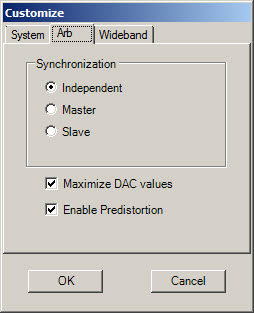
The MXG and EXG Internal Arbs come equipped with an internal calibration which is comparable to the N7620B corrections. This means that if the MXG or EXG calibration is enabled the Pulse Building corrections are not needed. Enable the MXG/EXG internal calibrations by checking on The Arb tab of the Customize… panel.

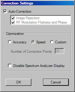
This menu item displays the  Correction
Settings dialog.
Select the type of corrections to use for the signal.
The dialog
enables and disables corrections. When enabled, corrections are applied
to downloaded waveforms and are based on certain system parameters, including:
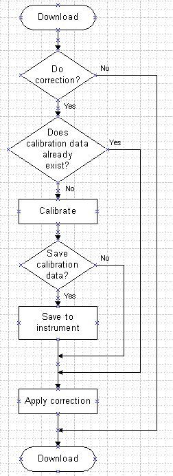
These parameters are used as a key into the calibration data
base kept in the Signal Generator. If an entry exist the corrections are
applied to the waveform. If no entry matches the key, a new calibration
measurement is made using the ESA/PSA spectrum analyzer. This measurement
data is added to the calibration data file and used to correct the waveform
as it is downloaded.
Click  here
to view the signal download flow diagram.
The Pulse Building application provides direct access for calibration.
Ensure that the signal generator, the arbitrary waveform generator and
spectrum analyzer share a common 10 MHz reference and are connected correctly.
Run the system Self Test if you are unsure of the system configuration.
The PSG/MXG/EXG/ESG signal generator has an automatic sensing 10 MHz reference
input. The ESA/PSA spectrum analyzer is not auto sensing and must be configured
to accept an external reference or to output a 10 MHz reference. External
arbitrary waveform generators are always configured for an external 10
MHz reference and the PSG/MXG/EXG/ESG internal Arb shares the same reference used
by the signal generator (see Equipment
Setup).
Auto-Correction
When this check box is enabled, the Pulse Building application's automatic
correction routine is used. This routine corrects for RF flatness and
image rejection. When Auto-Correction is enabled, both Image
Rejection and RF Modulation
Flatness and Phase are selected.
For best performance, an I/Q Calibration
from the signal generator's front panel is recommended on a regular basis.
The I/Q calibration should be done about once a week.
See also System
Optimization.
Optimization
The correction measurement can be optimized for accuracy or speed. Optimizing
for speed means that fewer measurement points are made. A waveform pre-distorted
with fewer data points may provide less correction to the linear distortions
in the hardware. Custom optimization lets you specify how many measurements
are made across the bandwidth for each correction. The actual number of
measurements made for Accuracy and Speed are configuration specific.
|
Internal I/Q
|
25
|
100
|
25-1000
|
|
External I/Q
|
25
|
100
|
25-1000
|
|
Wideband I/Q
|
50
|
200
|
25-1000
|
Disable Spectrum Analyzer
Display
This feature allows the spectrum analyzer display to be blanked during
the correction measurement. It can be used to hide operational frequencies
from general view.


