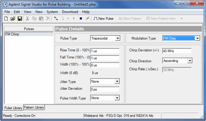
The carrier is frequency modulated based on the user-defined Chirp Deviation parameter. The Pulse Details form shown below displays the FM Chirp GUI selections.

is the maximum change in the modulation frequency that occurs over the time period of the pulse (Width (100%-100%)) parameter for trapezoidal and raised-cosine pulse types and from the first point of data through the last point of data for custom profile and custom I/Q pulse types. The deviation is a ± value around the carrier frequency, so the actual frequency deviation is twice that indicated in the Chirp Deviation text box.
is calculated and displayed as a read-only reference value. Chirp rate for a trapezoidal and raised-cosine pulse type is calculated as: Chirp Rate = Chirp Deviation / pulse width. The maximum Chirp Rate is 80 MHz/uSec: 80 MHz/uSec > Chirp Deviation / pulse width.
For example, a pulse width of 0.1 uSec and a Chirp Deviation of 4 MHz has a Chirp Rate of 80 MHz/uSec. (2x4MHz)/0.1 uSec.
can be ascending or descending and indicates an increase or decrease in frequency during the FM chirp.
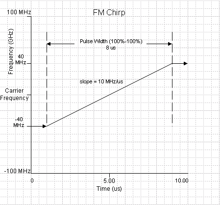
is held constant during pulse rise and fall times and is applied only during the duration of the pulse (Width (100%-100%)). In the form above the Chirp Deviation is ±40 MHz. During the pulse rise time the chirp frequency is 40 MHz below the carrier frequency. During the pulse width (100%-100%) the chirp frequency increases from 40 MHz below the carrier to 40 MHz above the carrier. During the fall time the chirp frequency is held at 40 MHz above the carrier.
The following figure shows the FM chirp deviation for the settings show above in the Pulse Details form.
