The pulse on/off ratio verification process is made with a spectrum/signal analyzer in zero span. The process is fairly simple and only requires a signal with a single pulse. Use the default parameter values unless otherwise noted. Corrections are not required and can be disabled.
This example was done using a Wideband I/Q configuration and a PSA Series Spectrum Analyzer.
Start the N7620B software and select the desired configuration (Wideband I/Q, External I/Q or Internal I/Q).
Disable Corrections. Verify that Enable Corrections is not checked on the Download menu.
Set the Pulse Width to 2 ms.
Create a new Pattern.
Add one item to the pattern.
Set the Repetition Interval to 4 ms.
Download and Play the pattern.
Set up the spectrum analyzer (SA) to view the signal.
Preset the spectrum analyzer.
Set the SA Frequency to the frequency of the signal generator (10 GHz in this case).
Set the Span to 0 Hz.
Set the Resolution Bandwidth (RBW) to 8 MHz, or its maximum value.
Set the Sweep Time to 5 ms.
Set up the SA to use an external trigger and use Marker 1 from the Arb as the trigger source. For Internal I/Q use Event 1 output from the signal generator.
Adjust the Trigger Level to get a stable signal.
Reduce the Resolution Bandwidth (RBW) to suppress broadband noise.
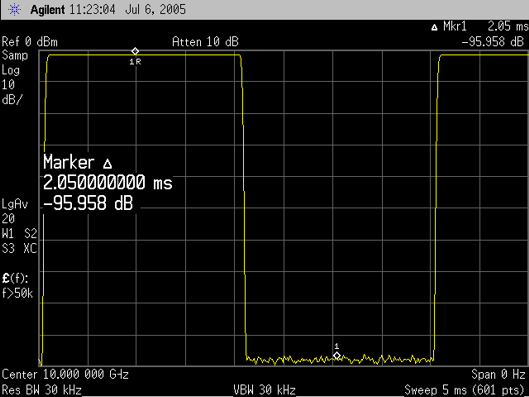
As the RBW is reduced some rounding of the pulse edges may occur. This is acceptable because you are only comparing the pulse amplitude at its mid-point to the amplitude at the mid-point of the off time. The following figure illustrates a pulse on/off ratio greater than 80 dBc.

Pulse On/Off Ratio at 10 GHz
To view only the On/Off ratio of the I/Q signal, turn off the ALC and the Pulse modulator and Download and Play the signal again.
The pulse On/Off ratio may appear significantly degraded with the pulse modulator disabled. This degradation can be caused by carrier leakage. Be sure to minimize the carrier leakage by enabling the I/Q Adjustments on the signal generator, and then adjusting both the I Offset and Q Offset values to minimize the carrier leakage.
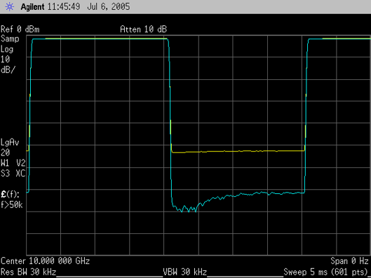
The following figure illustrates the pulse on/off ratio of just the I/Q signal, before and after the carrier leakage has been minimized. The top trace, between pulses, is before I and Q offset adjustments. The bottom trace, between pulses, is after the adjustments and shows an On/Off ratio of > 65 dBc.

Pulse On/Off Ratio Without the Pulse Modulator at 10 GHz