property page
shows <Simulated
Hardware> in the Name
and Connection cells, and N/A
in most of the other cells.
property page
shows <Simulated
Hardware> in the Name
and Connection cells, and N/A
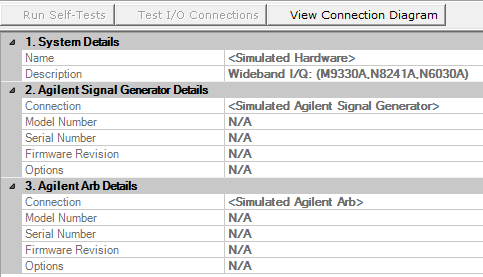
in most of the other cells.Select this view to display read-only information about the hardware
system. When using the Simulated Hardware
mode, the property page
shows <Simulated
Hardware> in the Name
and Connection cells, and N/A
in most of the other cells.
Descriptions in this section apply to both signal generators and arbitrary waveform generators (Arbs).
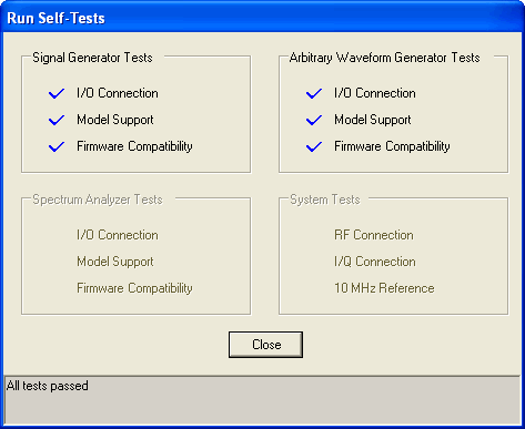
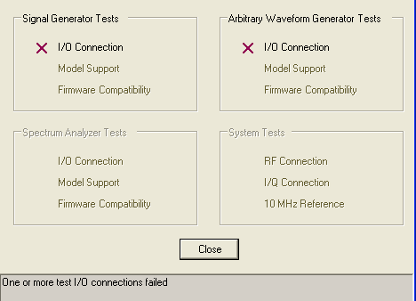
Click this button to run a hardware self-test. The self-test verifies the following:
the hardware has the proper firmware revisions
the hardware shares a common 10 MHz reference
the signal generator output is connected to the spectrum analyzer input
when used, the external Arb outputs are connected to the proper IQ inputs on the signal generator
The self-test can support external frequency translation or external gain. However, the user must set the frequency offset and/or the amplitude offset properties and download a signal. Downloading a signal sets the frequency offset and amplitude offsets. Executing a self test will now use the offsets. To disable the offsets for the self test, set the frequency offset and amplitude offset to zero and download a signal or reset the application by selecting File > New.
The Self-Tests window
appears and displays the results of the tests. Closing the test dialog
window returns the display from the Hardware node to the Multitone or
Noise Power Ratio node, depending upon which node is active.
If an error occurs during the self-test, a red X
appears next to the failed test and an error message is displayed in the
status area.
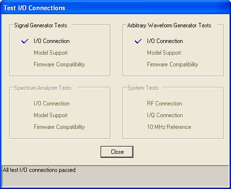
Click this button to run an I/O interface connection test between the hardware and the PC.
The Test I/O Connections window
appears and displays the results of the tests. Closing the test dialog
window returns the display from the Hardware node to the Multitone or
Noise Power Ratio node, depending upon which node is active.
If an error occurs, a red X
appears next to the failed I/O connection and an error message is displayed
in the status area.
Click this button to view the hardware connection diagram for the selected hardware configuration.
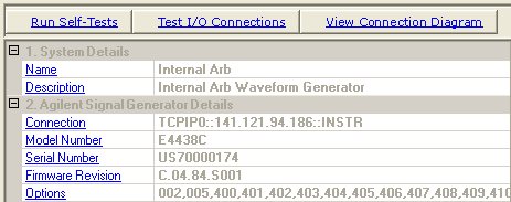
View the name assigned to the system when it is configured with the wizard.
View the hardware configuration type.
View the connectivity type, such as LAN or GPIB, and the associated address.
View the signal generator or Arb model number.
View the signal generator or Arb serial number.
View the signal generator or Arb firmware revision number.
View the list of options installed on the selected signal generator or Arb.
For a complete description of the available signal generator or Arb options, see the instrument's data sheet.