Modify the NPR Signal Amplitude Flatness
Amplitude Profile
The Amplitude Profile feature of the N7621 Multitone Distortion application allows you to modify the amplitude flatness of a Noise Power Ratio (NPR) signal. Two examples are presented here. Example 1 will work with most hardware configurations. Example 2 requires a PSG and a Wideband Arb. Both examples use the “TestAmplitudeProfile.txt” file included in the Multitone Distortion\ApiExample directory.
Example 1- Internal Arb
-
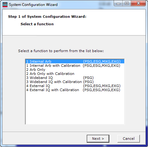
Start the software and configure
the system for a  Internal Arb Waveform Generator
with Calibration
using a PSG, ESG, MXG or EXG.
Internal Arb Waveform Generator
with Calibration
using a PSG, ESG, MXG or EXG.
-
From the Mode
menu, select Noise Power Ratio
(NPR).
-
Configure the NPR Signal Frequency and Amplitude as follows:
-
RF Output = On
-
Frequency = 1 GHz
-
Amplitude = 0 dBm
-
Configure the NPR Settings
as follows:
vale
-
Click  to download and play the waveform.
The text file TestAmplitudeProfile.txt
contains simulated data from 900 MHz to 1100 MHz and from 9 GHz to 11 GHz, and represents cable attenuation
versus frequency.
Amplitude Profile File
The Amplitude
Profile file
contains two columns. The first column is the absolute frequency in Hz,
the second column is the amplitude response in dB or dBm.
The data must be sorted from lowest frequency
to highest frequency without duplicate frequency data points. The application
interpolates between data points and uses the end points for frequencies
beyond the lowest and highest frequencies.
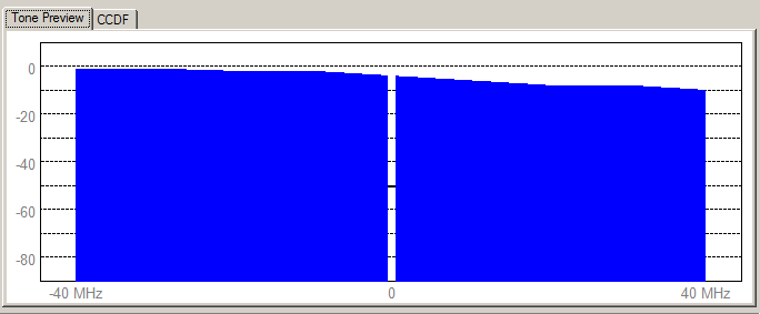
The figure below shows the amplitude profile
display of the NPR mode using the settings from step 1 through 4 above.
Amplitude Accuracy Adjustment Disabled (default)
When the Apply Amplitude Accuracy Adjustment
is disabled, the Amplitude Profile file must contain the measured amplitude
response of both the signal generator and the signal path outside of the
signal generator.
The figure below contains the amplitude
profile generated using the TestAmplitudeProfile.txt
data.
 Return to top
Example 2 - Wideband Arb
-
Start the software and configure
the system for a Wideband Arb Waveform Generator
with Calibration
using the N6030A Arb.
-
From the Mode
menu, select Noise Power Ratio
(NPR).
-
Configure the NPR Signal Frequency and Amplitude as follows:
-
RF Output = On
-
Frequency = 10 GHz
-
Amplitude = 0 dBm
-
Configure the NPR Settings
as follows:
-
Click to download and play the waveform.
The text file TestAmplitudeProfile.txt
contains simulated data from 9 GHz to 11 GHz and represents cable attenuation
versus frequency, as shown in the figure below.
Amplitude Profile File
The Amplitude
Profile file
contains two columns. The first column is the absolute frequency in Hz,
the second column is the amplitude response in dB or dBm.
The data must be sorted from lowest frequency
to highest frequency without duplicate frequency data points. The application
interpolates between data points and uses the end points for frequencies
beyond the lowest and highest frequencies.
The figure below shows the amplitude profile
display of the NPR mode using the settings from step 1 through 4 above.
The Amplitude Profile can be used with or
without the NPR application's Apply Amplitude
Accuracy Adjustment.
Amplitude Accuracy Adjustment Disabled (default)
When the Apply Amplitude Accuracy Adjustment
is disabled, the Amplitude Profile file must contain the measured amplitude
response of both the signal generator and the signal path outside of the
signal generator.
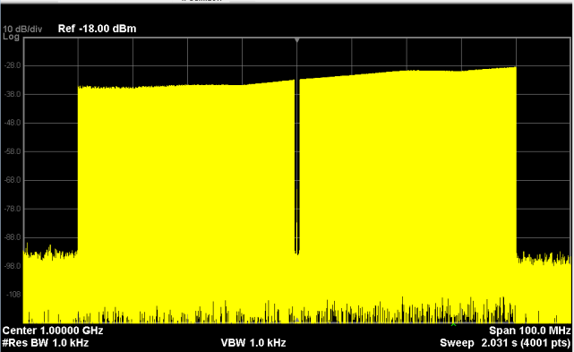
The figure below contains the amplitude
profile generated using the TestAmplitudeProfile.txt
data.
|

|
The ripple in the plot is from the RF output
path of the signal generator. The TestAmplitudeProfile.txt file does not
contain any information to correct the RF signal generator output profile.
|
Amplitude Accuracy Adjustment Enabled
When the Apply Amplitude Accuracy Adjustment
is enabled, the correction measurement will characterize the amplitude
profile of the signal generator and signal path up to the spectrum analyzer.
It corrects for the signal generator flatness and then adds the correction
needed by the response in the Amplitude Profile file. The figure below
shows this correction.
|
|
When providing the amplitude profile of the
signal generator by sweeping a sine wave in the wideband I or Q input,
be sure to turn the ALC off.
|
There are several harmonic and/or spur filters
in the RF output path. Be sure to characterize the RF output on both sides
of the filter switch points. The following figures show the signal generator
amplitude response at 5 GHz and 5.000000001 GHz.
Flatness at 5 GHz
Flatness at 5.000000001 GHz (5.5 GHz low pass filter switched out)
Return
to top