If the Modulation Distortion Setup dialog is not displayed, press Freq> SA Frequency > MOD Setup....
The Sweep, RF Path, Modulate, or Measure tab functions can now be selected.
Select the Modulate
tab.
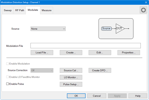
In the Modulate
tab, click on the Create...
button to access the Create Modulation
dialog.
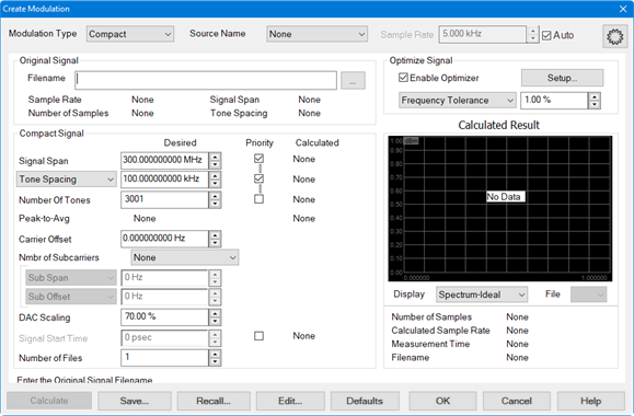
In the Modulation
Type pull down menu, select NPR
Notch.
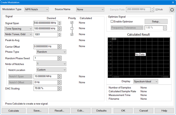
In the Source Name pull down menu, select the source. If it is not in the list, select Add Source... then refer to Set Up the External Source to set up a source.
Click on the Calculate button then under Calculated Result, verify that the signal looks reasonable.
To make adjustments to the settings, perform the following procedure (optional):
To adjust the frequency span of the modulated carrier, click in the Signal Span data entry field then use the up/down arrows or double-click in the data entry field then enter the frequency using the displayed keypad.
To adjust the distance between each tone, click in the Tone Spacing data entry field then use the up/down arrows or double-click in the data entry field then enter the frequency using the displayed keypad.
To adjust the number of odd or even tones, select either Nmbr Tones, Odd or Nmbr Tones, Even, click in the data entry field, then use the up/down arrows to make a change. This setting forces the optimizer to choose an odd or even number of tones. The optimizer will also choose an offset such that the carrier lands on one of the tones.
To adjust the carrier offset value relative to the carrier LO frequency, click in the Carrier Offset data entry field then use the up/down arrows or double-click in the data entry field then enter the frequency using the displayed keypad.
To select a phase type, click on the Phase Type pull down menu then select Random, Fixed, or Parabolic. The Random Phase Seed sets the phase seed when Random phase is the Phase Type.
To set the number of notches, select the Nmbr of Notches pull down menu and select up to 3 notches.
To set the notch location, select the Notch Location pull down menu and select Custom, Symmetric, or Avoid Carrier.
Custom selection allows the user to define the notch span using Notch1 Span and notch offset using Notch1 Offset.
Symmetric selection locates the notch in the center of the Signal Span and allows the notch span to be changed using Notch1 Span.
Avoid Carrier selection locates the notch near the center of the Signal Span but will be shifted to avoid the LO carrier feedthrough and allows the notch span to be changed using Notch1 Span.
To adjust the the scaling factor used for the waveform (full scale = 100%), click in the DAC Scaling data entry field then use the up/down arrows or double-click in the data entry field then enter the value using the displayed keypad. This ensures that the DAC filter does not output a signal that is larger than the DAC's maximum output level, which can cause distortion in the system. Setting the scaling factor to 100% will usually cause excessive distortion.
With the Enable Optimizer check box checked, the calculated modulated signal will be optimized according to the constraints defined in Optimize Signal group box. For more information, refer to the description for Enable Optimizer and the Optimizer Setup dialog.
To adjust the allowed tolerance for tone spacing when calculating the modulation signal, select Frequency Tolerance from the Optimize Signal pull down menu, click in its data entry field, then use the up/down arrows or double-click in the data entry field then enter the tolerance using the displayed keypad.
To adjust minimum period of the waveform greater than or equal to the specified value (seconds), select Min Waveform Period from the Optimize Signal pull down menu, click in its data entry field, then use the up/down arrows or double-click in the data entry field then enter the period using the displayed keypad.
To adjust minimum number of tones greater than or equal to the specified value, select Min Number of Tones from the Optimize Signal pull down menu, click in its data entry field, then use the up/down arrows or double-click in the data entry field then enter the number of tones using the displayed keypad. This will ignore the Number of Tones selection.
To adjust maximum tone spacing less than or equal to the specified value (Hz), select Max Tone Spacing from the Optimize Signal pull down menu, click in its data entry field, then use the up/down arrows or double-click in the data entry field then enter the maximum tone spacing using the displayed keypad. This will ignore the Tone Spacing selection.
After making any adjustments, click on the Calculate button then, under Calculated Result, verify that the signal looks reasonable.
Click the
Save... button and save the
NPR Notch file. The filename is displayed below the display window.
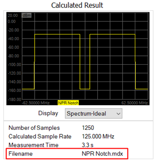
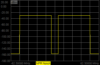
In the Display pull down menu, select Spectrum-Ideal. Signals similar
to the following should be displayed:
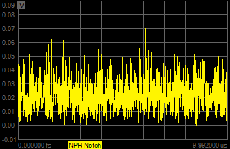
In the Display pull down menu, select Time. Signals similar to the following
should be displayed:
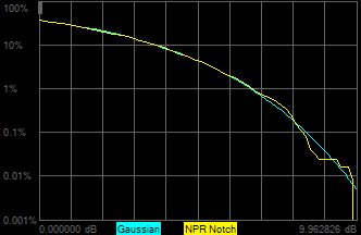
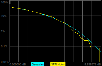
In the Display pull down menu, select CCDF. The following plot represents
the complementary cumulative distribution function (CCDF) curve of
the NPR Notch test signal, as well as the Gaussian distribution (pink
trace):
Increasing the number of tones results in the following:
Finer tone spacing.
Longer period for the test signal.
More accurate CCDF as shown below.