This topic applies to NA520xA PNA-X Pro models only.
Frequency Offset Mode (FOM) provides the capability to have the VNA Sources tune to frequencies that are different (offset) from the VNA Receivers.
In this topic:
See also, the following topics:
|
Using Hardkey/SoftTab/Softkey |
Using Menus: |
|
|
Note: For NA520xA PNA-X Pro models, each port has its own unique RF source, allowing more flexibility in path configurations, such as when using combiners.
Additionally, Option 2SS/4SS enables simultaneous sources, that is, the ability to turn on 2 or 4 sources at the same time. If you set a source ON and the number of simultaneous sources is exceeded, then the VNA automatically disables other sources and displays a warning in the status bar. If sources must be automatically disabled, the first sources to be disabled will be those currently in AUTO mode.
The following source selections are available:
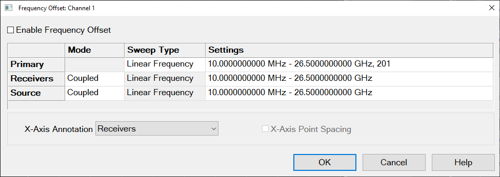
Enable Frequency Offset Enables Frequency Offset Mode (FOM) on ALL measurements that are present in the active channel.
When FOM is NOT enabled, all frequencies are the same as the active channel.
Tip: First make other settings on this dialog box, then click Enable Frequency Offset (checkmarked box = ON).
Primary The current Active Channel settings. When a Source or Receiver is coupled to the Primary settings, its Sweep Type is the same as that of the Primary. The frequency settings of the coupled range are mathematically derived from the Primary settings using the Multiplier, Divisor, and Offset values. With this approach, only the Primary settings need to be changed in order to affect change in the coupled Sources and Receivers. Changes to the Primary channel settings occur when Frequency Offset is checked ON. See example using Primary and Coupled setting.
Tip: Primary settings are ONLY used when Sources and Receivers are Coupled. It is often easier to Uncouple, then set Sources and Receivers independently.
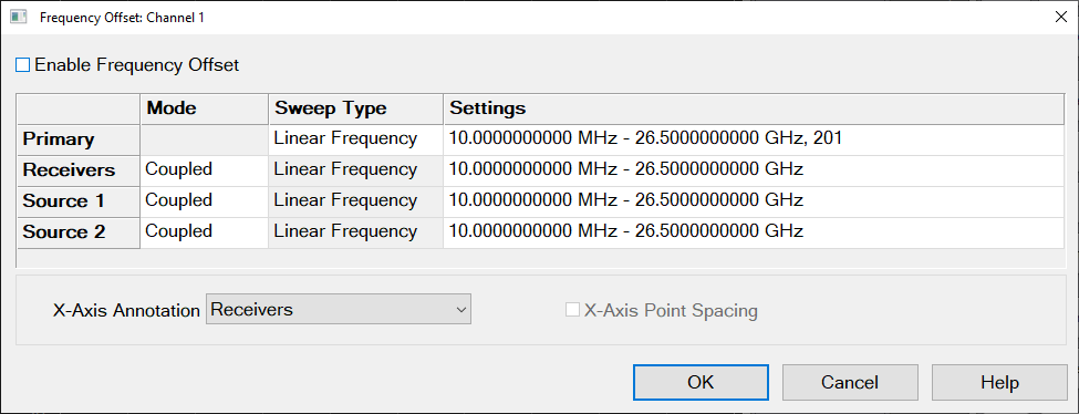
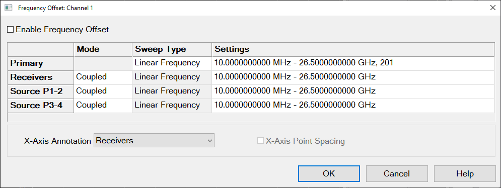
Source Rows For a standard source option, the VNA controls sources in pairs. Sources are labeled as "Source" in the 2-port. Sources are labeled as "Source 1-2" and "Source 3-4" in the 4-port.
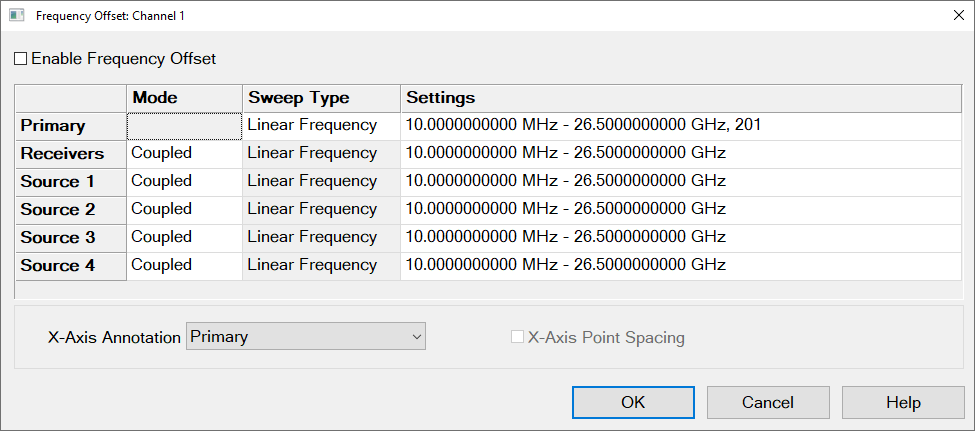
If the simultaneous source option (2SS/4SS) is enabled, VNA provides all independent sources. The sources are labeled as "Source 1", "Source 2", "Source 3", and "Source 4".
Receivers All receivers that are used in the channel, including Reference receivers, are tuned to the specified frequency settings.
Mode
Coupled Source and Receiver settings are mathematically derived from the Primary settings using Multiplier, Divisor, and Offset values. Learn more.
Uncoupled Source and Receiver settings are entered independently, without reference to Primary settings. When Uncoupled, Source and Receiver Ranges can use separate sweep types.
Sweep Type Click to change the type of sweep for each range. Only available for Primary and Uncoupled Sources and Receivers.
Settings To change settings, click IN the appropriate Settings cell, then click Edit.
If coupled, invokes the Coupled dialog.
If uncoupled or Primary invokes the Uncoupled settings dialog.
X-Axis Annotation Select the settings to be displayed on the X-Axis:
X-Axis Point Spacing Only available when a Segment Sweep Type is selected as the X-Axis display. Learn more.
|
Note: When Frequency Offset is enabled, ALL receivers on the channel, including the reference receivers, tune to the new offset frequencies, Therefore the source and reference receiver will be at different frequencies. Therefore, FOM measurements that include a reference receiver, which includes all S-parameters, display invalid data. To measure and display measurements at both the source and receiver frequencies, you must use two channels. Use Equation Editor to calculate the conversion loss. See a calibrated FOM conversion loss example. |
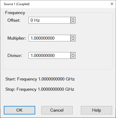
Coupled Formulas:
Range Start = [Primary Start x (Multiplier / Divisor)] + Offset
Range Stop = [Primary Stop x (Multiplier / Divisor)] + Offset
Where:
Offset Specifies an absolute offset frequency in Hz. For mixer measurements, this would be the LO frequency. Range is +/- 1000 GHz. Offsets can be positive or negative.
Multiplier Specifies (along with the divisor) the value to multiply by the stimulus. Range is +/- 1000.
Negative multipliers cause the stimulus to sweep in decreasing direction. For downconverter mixer measurements, this would be for setups requiring the Input frequency to be less than LO frequency. See an example.
0 (zero) as the multiplier nulls the Primary setting. Then the Offset value adds to zero.
Divisor Specifies (along with the multiplier) the value to multiply the stimulus. Range is 1 to 1000.
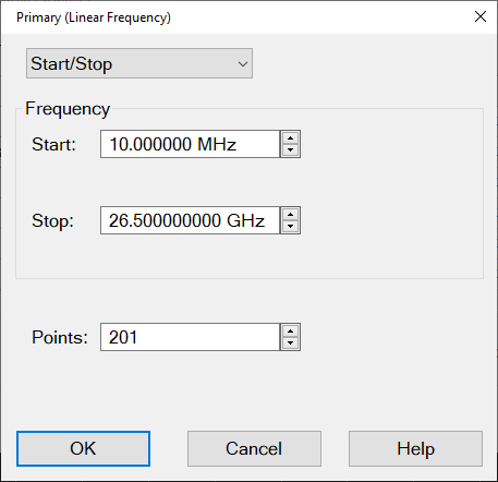
This dialog will vary depending on the sweep type:
Uncoupled Log sweep yields invalid data whenever the sources are offset from the receivers.
Select Start/Stop or Center/Span
Frequency Enter values
Points (Primary only) Enter number of data points for the sweep.
CW Freq Enter frequency in Hz.
Points (Primary only) Enter number of data points for the power sweep.
CW Freq Enter frequency in Hz.
Sweep Time Enter time to complete one sweep. Enter 0 for the fastest sweep.
For Advanced Users: Uncoupled Segment Sweep offers great flexibility in configuring measurements. In segment sweep mode:
The OK button is NOT available until the total number of data points for all segments matches the number of Primary data points.
Independent IF Bandwidth and Independent Sweep Time are available ONLY on the Primary (channel) and the Uncoupled Receivers - NOT Sources.
Independent Power is available ONLY on the Primary (channel) and the Uncoupled Sources - NOT Receivers.