5G NR
Updated for 38.104 (v17.9.0 2023-5). Learn more.
The Cell ID is assigned based on the current carrier index, i.e. Carrier 1 use Cell ID 1, Carrier 2 use Cell ID 2.
Remote Command - DL Test Model
User Interface - DL Test Model
|
SCPI Command |
[:SOURce]:RADio:NR5G:WAVeform[:ARB]:CCARrier<carrier>:CONFig:DTModel "Bandwidth: FR1BW3M|FR1BW5M|FR1BW10M|FR1BW15M|FR1BW20M|FR1BW25M|FR1BW30M|FR1BW35M|FR1BW40M|FR1BW45M|FR1BW50M|FR1BW60M|FR1BW70M|FR1BW80M|FR1BW90M|FR1BW90M|FR1BW100M|FR2BW50M|FR2BW100M|FR2BW200M|FR2BW400M|FR2BW800M|FR2BW1600M|FR2BW2000M, Numerology: MU0|MU1|MU2Ncp|MU3|MU5|MU6, DuplexType: TDD|FDD|BC3|UDEF, TestModel: FR1TM11|FR1TM12|FR1TM2|FR1TM2A|FR1TM2B|FR1TM31|FR1TM31A|FR1TM31B|FR1TM32|FR1TM33|FR2TM11|FR2TM2|FR2TM2A|FR2TM31|FR2TM31A, NumberOfLayers: <integer>, Modulation: QPSK|QAM16|QAM64, PhaseCompensation: AUTO|MANual|OFF, PayloadData: PN23|PN9 TDDSlotAllocation: <string> NumberOfDownlinkSymbols1: <integer>, NumberOfDownlinkSymbols2: <integer>, NumberOfDownlinkSymbols3: <integer>, NumberOfDownlinkSymbols4: <integer>" |
|
SCPI Example |
RAD:NR5G:WAV:CCAR:CONF:DTM "Bandwidth: FR1BW90M, Numerology: MU1, DuplexType: TDD, TestModel: FR1TM12, PhaseCompensation:AUTO, PayloadData: PN23" |
|
Couplings |
Parameters and default values of DL Test Model Config are listed below: Bandwidth: FR1BW100M Numerology: MU1 DuplexType: TDD TestModel: FR1TM11 NumberOfLayers: 1 Modulation: QAM64 PhaseCompensation: AUTO PayloadData: PN23 One combined string is needed to be inputted in SCPI command. The format of it is "name: value, name: value …". Default value will be used if parameter is not provided. The order of parameters does not matter. Parameter's name and value are case sensitive. If parameter's name is incorrect, error " -224, "Illegal parameter value; xxx is incorrect parameter name." will be generated. If parameter's type is enum and the supplied enum value is illegal, error " -224, Illegal parameter value; xxx has incorrect value." will be generated. |
|
Notes |
Modulation is only visible when TestModel is FR1TM2, FR2TM2 and FR2TM31. For SCPI user, modulation is only applicable when TestModel is FR1TM2, FR2TM2, FR2TM31 though you can input it even Test Model is not set to proper value. |
|
GUI Location |
Apps > 5G NR > Carrier DL > DL Test Model |
Choices:
Downlink: Based on the Table 5.3.2-1, 5.3.2-2, and 5.3.2-3 in 38.104
Uplink: Based on the Table 5.3.2-1 in 38.101-1 and 38.101-2
Selects the bandwidth configuration for the carrier.
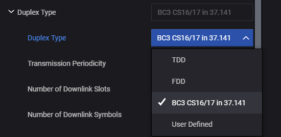
Choices: TDD | FDD | BC3 CS16/17 in 37.141 | User Defined
Selects the duplex type.
When TDD is selected, several TDD parameters appear below. These TDD parameters are reset to default values whenever numerology changes or FR changes. (The default values are different for each numerology.)
Sets the periodicity of DL-UL pattern. The choices are related to numerology.
Read-only.
Sets the number of consecutive full DL slots at the beginning of each DL-UL pattern. The range is related to the numerology and slot configuration period.
Read-only.
Range: 0 ~ 14 for Normal CP; 0 ~ 12 for Extended CP
Sets the number of consecutive DL symbols in the beginning of the slot following the last full DL slot.
Read-only.
Sets the number of consecutive full UL slots at the end of each DL-UL pattern. The range is related to the numerology and slot configuration period.
Read-only.
Range: 0 ~ 14 for Normal CP; 0 ~ 12 for Extended CP
Sets the number of consecutive UL symbols in the end of the slot preceding the first full UL slot.
Read-only.
Displays the number of special slots.
Read-only.
Displays the TDD slot allocation for one period.
Read-only.

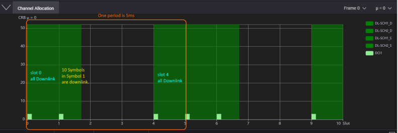
When BC3 CS16/17 in 37.141 is selected, the valid slots for downlink are set as defined in chapter E.0A in TS 37.141.
Table E.0A-1: Configurations
Field Name | 15 kHz SCS | 30 kHz SCS | 60 kHz SCS |
|---|---|---|---|
Tdd-UL-DL-Configuration |
| ||
referenceSubcarrierSpacing | 15 | 30 | 60 |
Periodicity (ms) for dl-UL-TransmissionPeriodicity | 5 | 5 | 5 |
nrofDownlinkSlots | 1 | 2 | 4 |
nrofDownlinkSymbols | 0 | 0 | 0 |
nrofUplinkSlots | 0 | 0 | 0 |
nrofUplinkSymbols | 0 | 0 | 0 |
Tdd-UL-DL-ConfigDedicated |
| ||
nrofDownlinkSymbols | For Slot#1: 10 | For Slot#3: 6 | For Slot#6: 12 For Slot#7: 0 |
nrofUplinkSymbols | For Slot#1: 2 | For Slot#3: 4 | For Slot#6: 0 For Slot#7: 8 |
slotIndex | 1 | 3 | 6,7 |
nrofDownlinkSymbols | 10 | 6 | 12,0 |
nrofUplinkSymbols | 2 | 4 | 0,8 |
slotIndex | 2,3 | 4,5,6,7 | 8,9,10,11,12,13,14,15 |
symbols | all Uplink | all Uplink | all Uplink |
slotIndex | 4 | 2,8,9 | 4,5,16,17,18,19 |
symbols | all Downlink | all Downlink | all Downlink |
For 15 kHz SCS, all symbols in slot 0 and slot 4 are used for downlink. 10 symbols in slot 1 are also used for downlink.

For 30 kHz SCS, all symbols in slot 0,1,2,8,9 are used for downlink. 6 symbols in slot 3 are used for downlink.

For 60 kHz SCS, all symbols in slot 0,1,2,3,4,5,16,17,18,19 are downlink. 10 symbols in slot 6 are used for downlink.

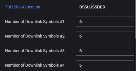
When User Defined is selected, there is a parameter “TDD Slot Allocation” that will define a TDD pattern. The pattern contains “D”, “U” and “S”.
D meams this slot is used for downlink only
U means this slot is used for uplink only
S means this slot is used for both downlink and uplink
If the length of “TDD Slot Allocation” is longer than the required slot in one period, it will be clipped to the number of slots in one period; if the length of “TDD Slot Allocation” is shorter than the required slot in one period, the other slot will not be used.
For “S” slot, there will be one or more parameters “Number of Downlink Symbols #”. There can be a maximum of 4 “S” in “TDD Slot Allocation”, so there can be 4 “Number of Downlink Symbols #” parameters and one for each “S” slots.

Selects the numerology of the
Choices: NR-FR1-TM1.1 | NR-FR1-TM1.2 | NR-FR1-TM2 | NR-FR1-TM2a | NR-FR1-TM2b |NR-FR1-TM3.1 | NR-FR1-TM3.1a | NR-FR1-TM3.1b |NR-FR1-TM3.2 | NR-FR1-TM3.3 | NR-FR2-TM1.1 | NR-FR2-TM2 | NR-FR2-TM2a | NR-FR2-TM3.1 | NR-FR2-TM3.1a
Default: NR-FR1-TM1.1
Selects the Test Model to configure. The choices are defined in the section 4.9.2 of 38.141. A description of the currently selected test model appears in the hint window directly below.
Choices: QPSK | 16QAM | 64QAM
Default: 64QAM
Set the Modulation Type for NR-FR1-TM2, NR-FR2-TM2 or NR-FR2-TM3.1.
Choices: 1 | 2
Sets the Number of Layers (Rank) for Test Model 1.1, two layers MIMO transmission is used for TAE requirement, single layer is used for others.
Choices: Auto | Manual | Off
Default: Auto
Set the phase compensation mode on the baseband signal before upconversion.
Phase compensation is not applicable for PRACH carrier.
Auto: Use the RF frequency from the instrument node.
Manual: Enter the RF frequency manually.
Off: Disable phase compensation on baseband signal.
Choices: PN9 | PN23
Default: PN23
Select the PN type for Downlink Test Model.