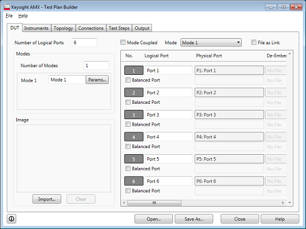
The DUT tab defines your DUT specifications.

Number of Logical Ports: Specify the number of logical ports in DUT.
Number of Modes: Specify the number of mode to define.
Mode n: Specify the name of Mode
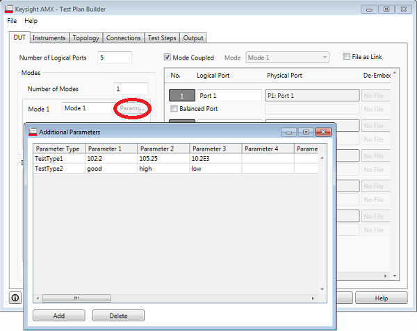
Params... : This allows you to define the parameters to output.

The defined parameters are transferred to TAP as shown below. Generally, users should modify the DUT Control plug-in in order to use these parameters for your DUT control.

Image: Save the figure of DUT. This helps you to setup the DUT more easily by viewing the figure of DUT. This image is shown at the Edit Test Step as well.
In order to eliminate the error factor of fixture/connector of DUT, the de-embedding, port extension delay and Loss function in VNA can be setup on the AMX.

Mode Coupled: The same setting is defined for all of modes
File as Link: The SnP file for de-embedding is not imported but it is referred to as link. De-embedding data can be updated by updating SnP file. The SnP file must be placed at the same path on the PC controller when the back-end application (TAP) is executed. When this is unchecked, the De-embedding data from SnP file is imported into test plan file.
Balance Port: Check if the logical port is balanced port. Two physical ports should be assigned to one logical port.
De-Embedding: Click "..." button to specify the SnP file. Click  button to clear the file setup.
Delay: Electrical delay in second for port extension.
Loss at DC, Loss1, @Freq1, Loss2, @Freq2:
In addition to port extension, you can set loss values for each port. By correcting loss due to port extension, more accurate measurement results are obtained.
There are two types of loss value settings: loss values at two frequency points for a specified port, and a DC loss value. You can make these settings at the same time for each port.
When you specify two frequency points, set the lower frequency to Loss1, and the higher one to Loss2
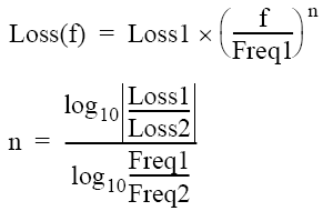
Expression to calculate loss using Loss 1:

Expression to calculate loss using Loss 1 and Loss 2:
