Other topics about Basic operations
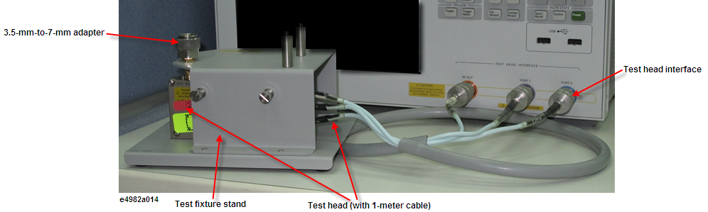
Connect the test head (with 1-meter cable) and test fixture stand to the E4982A as shown in the below figure. The figure does not show the test fixture for connection of the DUT (which will be installed on the test head). Open/short/load calibration at the 7-mm-terminal on the tip of the test head is described later.
Attach the test head to the test fixture stand with two screws. At this point, do not tighten the screws completely.
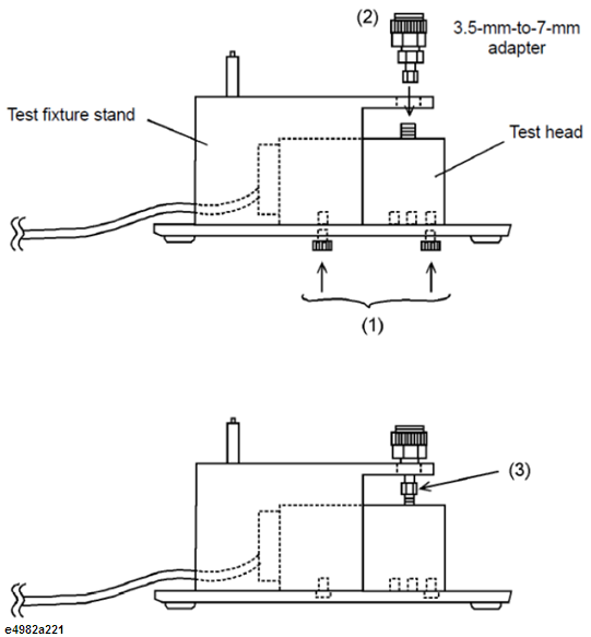
Align the 3.5-mm-to-7-mm adapter with the hole in the test fixture stand and gently insert the adapter.
Tighten the connector nut of the 3.5-mm connector with the provided wrench (for 3.5 mm/SMA connector).
Firmly, tighten the two screws.
Attach the three N(m)-SMA(f) adapters to the RF OUT, PORT 1, and PORT 2 terminals of the E4982A test head interface. Connect the three SMA(m) connectors (RF OUT, PORT 1, PORT 2) of the test head cable to the SMA(f) terminals of the adapters. Then tighten each of the connectors using the provided wrench (for 3.5-mm/SMA connector).
Be sure to use the provided wrench (for 3.5 mm/SMA connector) when tightening the connector nut of the 3.5-mm connector. Using another wrench could result in damage to the connector, which would cause incorrect measurements in the future.
Press the standby switch in the lower-left area of the E4982A front panel to turn ON the power.
Extra caution is required when you power ON or OFF the E4982A.
Under normal circumstances, always press the standby switch, or send the shutdown command from the external controller, to actuate the E4982A shutdown process. Never cut OFF the power supply directly by disconnecting the power cable plug from the rear panel of the unit.
If the power supply is cut OFF directly by disconnecting the power cable plug or by disconnecting the power supply to the AC outlet, the shutdown process will not be carried out, and there is a risk of damage to the software or hardware of the E4982A.
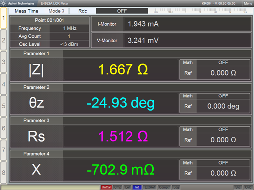
When the standby switch is pressed, the E4982A starts the self-test. After confirmation of normal operation, the measurement display appears based on the power-on default settings. The below figure is an example of a display when power is turned ON and the default setting is single point measurement display.