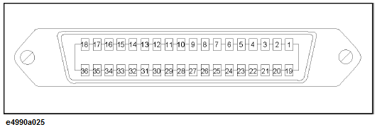
The layout of the I/O signal pins on the handler interface connector and its description are shown below.

A slash (/) symbol preceding signal names means that they are negative logic (active low).
Pin number Signal name Signal specification
|
Pin Number |
Signal |
Signal Specification |
|
1 |
GND |
0 V. Ground |
|
2 |
/INPUT1 |
When this port receives a negative pulse, /OUTPUT1 and /OUTPUT2 are changed to the Low level. |
|
3 |
/OUTPUT1 |
Changes to the Low level when /INPUT1 receives a negative pulse. A command is available for altering the Low/High level logic. |
|
4 |
/OUTPUT2 |
Changes to the Low level when /INPUT1 receives a negative pulse. A command is available for altering the Low/High level logic. |
|
5 |
/PORT A0 |
Bit 0 of port A (8 bit parallel output port). |
|
6 |
/PORT A1 |
Bit 1 of port A. |
|
7 |
/PORT A2 |
Bit 2 of port A. |
|
8 |
/PORT A3 |
Bit 3 of port A. |
|
9 |
/PORT A4 |
Bit 4 of port A. |
|
10 |
/PORT A5 |
Bit 5 of port A. |
|
11 |
/PORT A6 |
Bit 6 of port A. |
|
12 |
/PORT A7 |
Bit 7 of port A. |
|
13 |
/PORT B0 |
Bit 0 of port B (8 bit parallel output port). |
|
14 |
/PORT B1 |
Bit 1 of port B. |
|
15 |
/PORT B2 |
Bit 2 of port B. |
|
16 |
/PORT B3 |
Bit 3 of port B. |
|
17 |
/PORT B4 |
Bit 4 of port B. |
|
18 |
/PORT B5 |
Bit 5 of port B. |
|
19 |
/PORT B6 |
Bit 6 of port B. |
|
/INDEX |
Indicates that analog measurement is complete. The /INDEX signal changes to the Low level when analog measurement (all sweeps of all channels) is complete. When the handler receives the signal, it assumes that it is ready to connect the next DUT. However, no measurement data is available until data calculation is completed. When the point trigger function is ON, it goes to the High level before starting measurement of the first measurement point and returns to the Low level after completing measurement of all measurement points. |
|
|
20 |
/PORT B7 |
Bit 7 of port B. |
|
/READY FOR TRIGGER |
Indicates that the instrument is ready for triggering. This signal is changed to the Low level when the instrument is ready to receive a trigger signal. The /READY FOR TRIGGER signal goes to the Low level when the instrument is ready to accept the trigger signal for the first point and goes to the High level when the trigger signal for the first point is received. When the point trigger is OFF: When measurement of all measurement points is completed and the instrument is ready to receive the trigger signal for the first point of the next sweep, this signal goes to the Low level again. When the point trigger is ON: When each measurement point is completed and the instrument is ready to receive the trigger signal for the next measurement point, this signal goes to the Low level again. |
|
|
21 |
/PORT C0 |
Bit 0 of port C (4 bit parallel I/O port). |
|
22 |
/PORT C1 |
Bit 1 of port C. |
|
23 |
/PORT C2 |
Bit 2 of port C. |
|
/PORT C3 |
Bit 3 of port C. |
|
|
25 |
/PORT D0 |
Bit 0 of port D (4 bit parallel I/O port). |
|
26 |
/PORT D1 |
Bit 1 of port D. |
|
27 |
/PORT D2 |
Bit 2 of port D. |
|
28 |
/PORT D3 |
Bit 3 of port D. |
|
29 |
PORT C STATUS |
Port C status signal. This signal is changed to the High level when the port C is configured to output port. It is changed to the Low level when the port is configured to input port. |
|
30 |
PORT D STATUS |
Port D status signal. This signal is changed to the High level when the port D is configured to output port. It is changed to the Low level when the port is configured to input port. |
|
31 |
/WRITE STROBE |
A output port write strobe signal. When data is present (that is, output level changes) on any of the output ports, this signal provides a negative pulse. |
|
32 |
+5V pull-up |
Provides +5V DC power supply for external instruments. |
|
33 |
/SWEEP END |
A sweep completion signal. When measurement (all sweeps of all channels) and data calculation are completed, this signal provides a negative pulse. |
|
34 |
+5V |
Provides +5V DC power supply for external instruments. |
|
35 |
/PASS FAIL |
Each limit test's results signal. This signal changes to the High level when limit test, or bandwidth test results return FAIL. It changes to the Low level when all limit test results return PASS. |
|
36 |
/PASS FAIL STROBE |
Each limit test's results write a strobe signal. When limit test result is present on /PASS FAIL, this signal provides a negative pulse. |
Pin 19 has 2 features: Port B6 and INDEX. This feature is controlled by CONT:HAND:EXT:IND:STAT command.
Pin 20 has 2 features: Port B7 and READY FOR TRIGGER. This feature is controlled by CONT:HAND:EXT:RTR:STAT command.