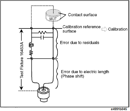
Calibration is performed by using the MUT connection plane of the 16453A test fixture as the calibration reference plane. By performing calibration on the MUT connection plane, you can eliminate errors due to the test fixture’s residuals and electric length. Therefore, unlike impedance measurement, electric length or fixture compensation is not required.
|
Correction |
Impedance measurement |
Dielectric measurement |
|
Calibration reference surface |
7-mm terminal (usual) |
MUT connection plane |
|
Electrical length setting |
Required |
Not required |
|
Fixture compensation |
Required |
Not required |
Perform calibration by following these steps:
Press the Cal > Accessory > 16453A.
Press the Cal > Compen Point > Fixed freq|User freq to select the measurement points used for user calibration or those for fixture compensation.
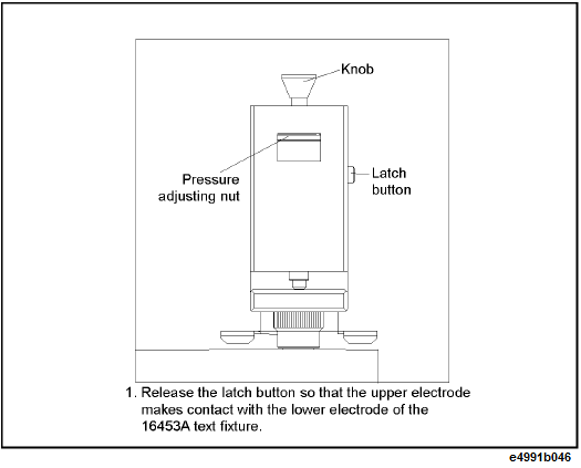
Set the MUT connection plane of the test fixture to the SHORT state.
Press Cal > Calibration > Execute Cal > Short.
A check mark, √ appears on the left side of Short softkey upon completion of the SHORT calibration data measurement.
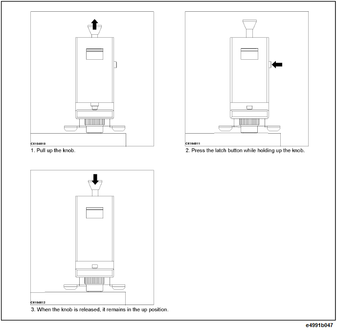
Set the MUT connection plane of the test fixture to the OPEN state.
Press Cal > Calibration > Execute Cal > Open.
A check mark, √ appears on the left side of Open softkey upon completion of the OPEN calibration data measurement.
Connect the load standard supplied with the 16453A test fixture to the test fixture by inserting it between the electrodes of the test fixture.
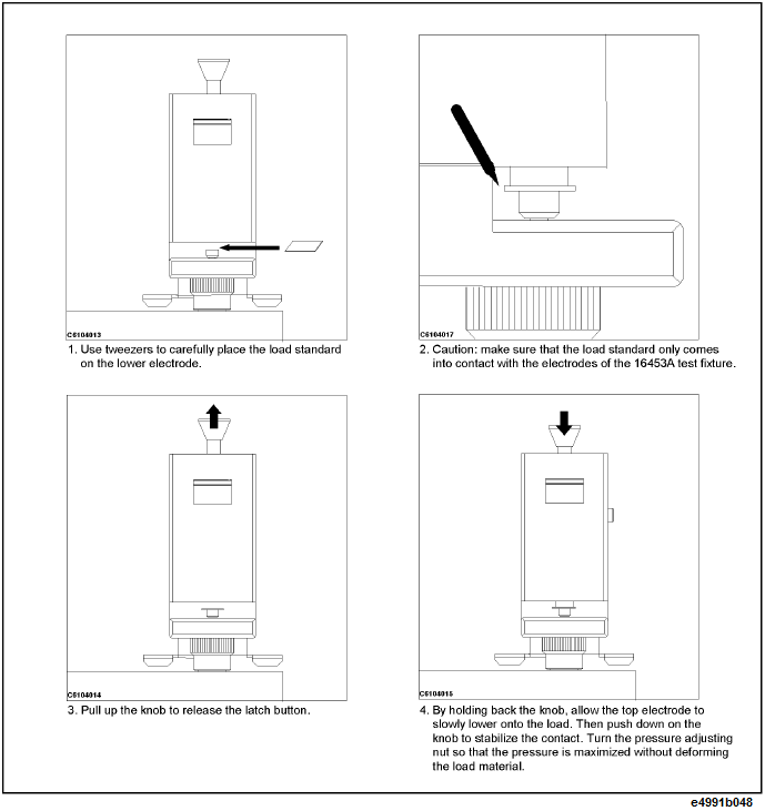
When connecting a load standard or a MUT to the test fixture, make sure that it only comes into contact with the test fixture’s electrodes. Also, be careful not to give the upper electrode horizontal pressure by moving the load standard or the MUT while it is in position between the electrodes.
Press Cal > Calibration > Execute Cal > Load.
A check mark, √ appears on the left side of Load softkey upon completion of the LOAD calibration data.
Confirm that all of the calibration data measurement is completed and then press Done.