The E4991B has a specified measurement accuracy at the 7-mm terminal (calibration reference plane) of a test head. However, in actual measurement, a measurement circuit (test fixture) is placed between the DUT connection terminal and the 7-mm terminal, and the influence of this circuit is included in the measurement result as a part of the DUT. Therefore, fixture compensation must be performed to remove the parasitic error that exists between the DUT connection terminal and the 7-mm terminal.
This section describes fixture compensation by using the 16197A as an example. When using other test fixtures, follow the procedure described in the Operation Manual of the test fixture.
Perform OPEN compensation to correct stray admittance due to the test fixture.
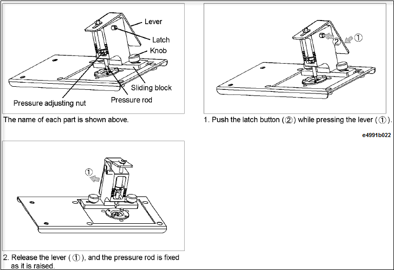
Set the DUT connection terminal of the test fixture to the OPEN state by following the procedure described in figure below. When using other test fixtures, follow the procedure described in the Operation Manual of the test fixtures.
Press Cal > Fixture Compen > Open (0 S 0 F 0 s).
OPEN compensation data measurement appears as ON - Cal > Fixture Compen > Open > ON.
Perform SHORT compensation to correct residual admittance due to the test fixture.
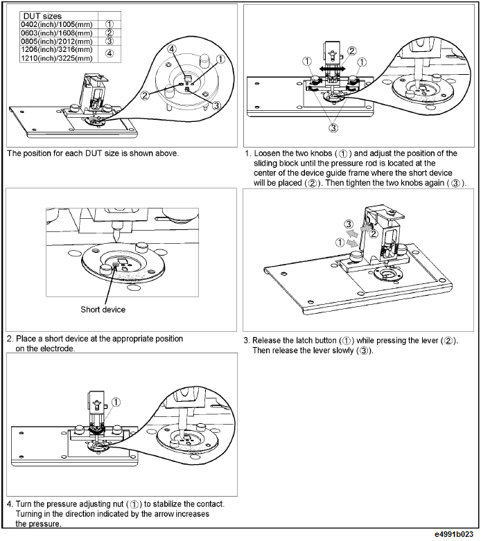
Connect a short device to the test fixture. Follow the procedure illustrated in the below figure to set the DUT connection terminal of the test fixture to the SHORT state. When using other test fixtures, follow the procedure described in the Operation Manual of the test fixture.
Press Cal > Fixture Compen > Short (0 Ω 0 H 0 s).
SHORT compensation data measurement appears as ON - Cal > Fixture Compen > Short > ON.
Upon completion of all fixture compensation data, you should use the E4991B to calculate the fixture compensation coefficient from the measured fixture compensation data. The coefficient is automatically saved to the internal memory.
Confirm that all compensation data measurement is completed.
Verify that the display of the status bar on the bottom of the screen changes to COMP OS.
After completing the fixture compensation, use the marker function to check that the SHORT compensation data has been measured correctly.
Press Meas > Trace 1 > |Z|.
Press Scale > Autoscale.
Press Marker > Marker 1.
Turn the rotary knob to check that trace values of measurement parameter |Z| are lower than 50 mΩ for all stimulus values. If not, place the short device on both electrodes again, align the location of the test fixture’s pressure rod, and repeat the fixture compensation.
When changing the location of the pressure rod after performing fixture compensation, you must again obtain the fixture compensation data.