This section describes hardware configurations and setups when using the E5053A Microwave Downconverter with the E5052B.
Following devices are required when configuring the E5052B and E5053A Microwave Downconverter:
E5052B
E5053A Microwave Downconverter
RF cables of 2 types × 2 (supplied with the E5053A, Keysight part number: E5053-61621, E5053-61622)
USB cable (supplied with the E5053A, Keysight part number: 8121-1695)
BNC cable (supplied with the E5053A, Keysight part number: 8120-1839)
BNC adapter (supplied with the E5053A, Keysight part number: 1250-1859)
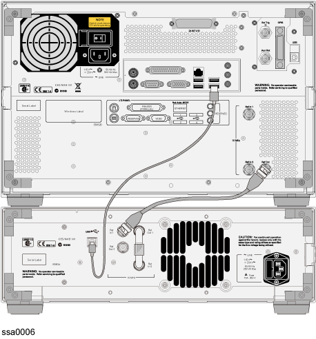
Check the following connections on the rear panel before turning on both the E5052B and the E5053A, as shown in Connection of the E5052B and the E5053A (rear view).
USB Cable (PN: 8121-1695): Connecting the USB ports of both the E5052B and E5053A.
BNC Cable (PN: 8120-1839): Connecting the E5052B internal reference signal output port (Ref Out) and the E5053A external reference signal input port (Ref In) of the channel 1.
BNC Adaptor (PN: 1250-1859): Connecting the internal reference signal output port (Ref Out) of the channel 1 and the internal reference signal input port (Ref In) of the channel 2 on the E5053A rear panel.
Connection of the E5052B and the E5053A (rear view)
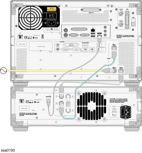
When the narrow-narrow mode in the transient measurement is selected, the Ref Out 2 connector on the E5053A should be connected with the Ref In 1 connector on the E5052B as shown in the following figure. If external signal source is used, is should be connected with the Ref In 2 connector on the E5052B.
Connection of the E5052B and the E5053A (rear view) : Narrow-Narrow Mode
Do not connect or disconnect the USB cable during the measurement.
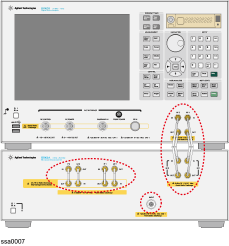
Check the following connections on the front panel as shown in Connection of E5052B and E5053A (front view).
RF Cable (PN: E5053-61621): Connecting the E5052B RF output ports and the E5053A RF input ports
RF Cable (PN: E5053-61622): Connecting the E5052B RF input ports and the E5053A RF output ports
When mounting the E5053A and the E5052B with the rack mount kit, use the following RF cables.
RF Cable (PN: E5053-61623): Connecting the E5052B RF output ports and the E5053A RF input ports
RF Cable (PN: E5053-61624): Connecting the E5052B RF input ports and the E5053A RF output ports
Connection of E5052B and E5053A (front view)
Use the torque wrench when the semi-rigid cable or adapter is fastened on the following connectors of E5052B and E5053A. The recommended torque and open-ended wrenches are shown below.
|
Connector |
Recommended Torque |
Recommended Wrench |
|
SMA |
5.7 kgf-cm (56 N-cm/ 5 in-lb) |
Wrench PN 8710-1582 |
|
3.5 mm |
9.2 kgf-cm (90 N-cm/ 8 in-lb) |
Wrench PN 8710-1765 |
Turn on the E5053A Microwave Downconverter first, and then turn on the E5052B.
The E5052B automatically detects the E5053A Microwave Downconverter whenever it is connected. If there's an auto recall file, the instrument state is also set along with the settings defined in the auto recall file.
When the E5052B fails to detect the downconverter and you try to activate the E5053A Microwave Downconverter, "No downconverter unit connected" error message is displayed. In this case, the E5052B instrument state is initiated as the settings of the E5052B standalone by the firmware, even if there's an auto recall file that includes any instrument setups that relate the E5053A settings.
See also Selecting Device Configuration for more information.