VCO Measurement

This section describes the process to evaluate different parameters of a VCO (Voltage Controlled Oscillator) using the E5052B. The VCO used for this example has the following specification:

Parameter

Value

Vcc (Bias Voltage)

5 ± 0.5 V

Vt (Tuning Voltage)

+1.0 ~ +4.5V

RF Output

800 ± 30 MHz


  1. Setting measurement conditions

    1. Preset the E5052B to factory settings by Preset > Factory.

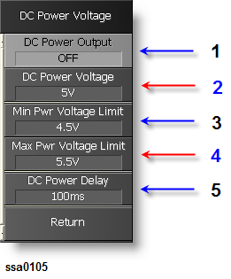
    2. Set DUT (VCO) Bias Voltage (Vcc) Settings by DC Power:

      • Set Min Pwr Voltage Limit as 4.5 V (3 in the figure below).

      • Set Max Pwr Voltage Limit as 5.5 V (4 in the figure below).

      • Set DC Power Delay as 100ms (5 in the figure below).

      • Set DC Power Voltage as 5V (2 in the figure below). 


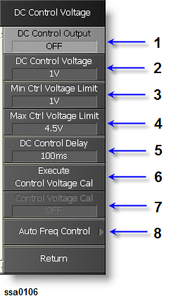
    1. Set DUT (VCO) Tuning Voltage (Vt) Settings by DC Control:

      • Set Min Ctrl Voltage Limit as 1.0 V (3 in the figure below).

      • Set Max Ctrl Voltage Limit as 4.5 V (4 in the figure below).

      • Set DC Control Delay as 100ms (5 in the figure below).

      • Set DC Control Voltage as 1V (2 in the figure below).


  2. Connecting the Device Under Test (DUT)

      1. Connect DUT to E5052B.

    1. Set DC Power > DC Power Output ON

    2. Set DC Control > DC Control Output ON

    3. Set Display > Update

  1. Making Measurements

    1.  Phase Noise

      1. Measurement

      1. Press Meas/View > Phase Noise to activate Phase Noise window. Press Window Max to maximize the window

      2. Press Setup > Frequency Band > 250M-7GHz

      3. Press Trigger > Trigger to Phase Noise > Continuous to start measurements

      4. Press Start/Center (Stop/Span), set Start > 100Hz and Stop > 40MHz

      5. Press Attn > Input Attenuator 0dB for best dynamic range. Press Entry Off to clear the warning message that appears at bottom left

      6. Press Avg/BW > Avg factor 8 > Averaging > ON to reduce fluctuation

      7. Press Scale > Auto Scale

B. Auto Frequency Control

If the 1 GHz signal is a signal of a VCO, you can control the frequency of the signal by using the automatic frequency control (AFC) function.

      1. Press DC Control > Auto Freq Control.

      2. Set Target > 1GHz.

      3. Set Tolerance > 10kHz.

      4. Set Sensitivity > 10MHz/V.

      5. Press AFC Status, then turn “ON” to activate AFC. When “AFC out of loop” message is displayed, change the value for tolerance or sensitivity to a value larger than the current setting.

C. Analysis Using Marker

      1. Press Marker > Marker1 > 20 > x1 to check phase noise at 20MHz offset

    1. Spectrum Monitor

      1. Measurement

      1. Press Meas/View > Spectrum Monitor to activate Spectrum window.

      2. Press Window Max to maximize the window.

      3. Press Trigger > Trigger to Spectrum Monitor > Continuous to start measurements

      4. Press Start/Center (Stop/Span), set Center to carrier frequency displayed in phase noise window.

      5. Press Setup > Reference Level > 5dBm to specify maximum input level of the measurement signal that is input from the RF IN port.

      6. Press Scale > Auto Scale

      1.  Analysis Using Marker

      1. Press Marker Search > Search Max

    2. Frequency and Power

      1. Measurement

      1. Press Meas/View > Freq & Power to activate Frequency and Power window. Press Window Max to maximize the window

      2. Press Setup > Frequency Band > 250M-7GHz

      • Tester Mode

        1. Press Setup > Frequency Resolution > 10Hz

        2. Press Trigger > Mode > Tester

        3. Press Trigger > Trigger to Freq & Power > Continuous to start measurements

      • Analyzer Mode

        1. Press Trigger > Mode > Analyzer

        2. Press Setup > Sweep Parameter > Control Voltage

        3. Press Setup > Frequency Resolution > 10Hz

        4. Press Setup > Points > 51 to perform tuning selectivity measurement  

        5. Press Start/Center (Stop/Span) > DC Control Start 1V > DC Control Stop 4.5V

        6. Press Scale > Auto Scale All

        7. Press Setup > Sweep Parameter > Power Voltage to perform frequency pushing measurement

        8. Press Start/Center (Stop/Span) > DC Power Start 4.5V > DC Power Stop 5.5V

        9. Press Scale > Auto Scale All

        10. Using touch screen touch Frequency screen to activate. Press Format > Frequency Format > Hz/V

        11. Press Scale > Auto Scale All

      1. Analysis Using Marker

      • Tuning Sensitivity

      1. Press Marker > Marker1 > 1 > Enter

      2. Press Marker > Marker2 > 1.5 > Enter

      3. Press Marker > Marker3 > 2 > Enter

      4. Press Marker > Marker4 > 2.5 > Enter

      5. Press Marker > Marker5 > 3 > Enter

      6. Press Trace Next to select Power trace in Frequency and Power window and repeat steps 1 to 5.

      7. Press Trace Next to select Current trace in Frequency and Power window and repeat steps 1 to 5.

      8. Press Trace Next to select Freq trace in Frequency and Power window and repeat steps 1 to 5.

      • Frequency Pushing

      1. Press Marker > Marker1 > 4.5 > Enter

      2. Press Marker > Marker2 > 4.7 > Enter

      3. Press Marker > Marker3 > 5 > Enter

      4. Press Trace Next to select Power trace in Frequency and Power window and repeat steps 1 to 3.

      5. Press Trace Next to select Current trace in Frequency and Power window and repeat steps 1 to 3.

      6. Press Trace Next to select Freq trace in Frequency and Power window and repeat steps 1 to 3.

    3. AM Noise Measurement

      1. Measurement

      1. Press Meas/View > AM Noise to activate AM Noise window. Press Window Max to maximize the window

      2. Press Setup > Frequency Band > 250M-7GHz

      3. Press Trigger > Trigger to AM Noise > Continuous to start measurements

      4. Press Start/Center (Stop/Span), set Start > 100Hz and Stop > 40MHz

      5. Press Attn > Input Attenuator 0dB for best dynamic range. Press Entry Off to clear the warning message that appears at bottom left

      6. Press Avg/BW > Avg factor 8 > Averaging > ON to reduce fluctuation

      7. Press Scale > Auto Scale

      1. Analysis Using Marker

      1. Press Marker > Marker1 > 100 > x1

      2. Press Marker > Marker2 > 1 > k/m

      3. Press Marker > Marker3 > 1 > M/μ

      4. Press Marker > Marker4 > 40 > M/μ


  1. Outputting measurement results