This topic describes the Keysight vector network analyzers (VNA) implementation of the NIST Multiline Thru Reflect Line (TRL) calibration algorithm. The Keysight implementation also supports a Multiline Thru Short Delay (TSD) calibration algorithm. This topic describes how to set up and use a calibration kit definition that will cause the VNA to do a Multiline TRL. It also discusses the various options that can be specified and how they interact with the standards as defined in Keysight calibration kits.
In this topic:
The Multiline TRL algorithm is based on the NIST Multiline TRL calibration algorithm called MultiCal[1][2]. It provides an over-determined solution when multiple LINE standards are used. The TRL algorithm (Legacy TRL) that existed prior to Multiline TRL being added is still available for use. If the Multiline TRL check box is selected, then the Multiline TRL algorithm will be used when the defined calibration kit is used for TRL calibration. The Legacy TRL algorithm allowed multiple LINE standards to be used, but for any given frequency only one LINE standard is used with the THRU and REFLECT standards.
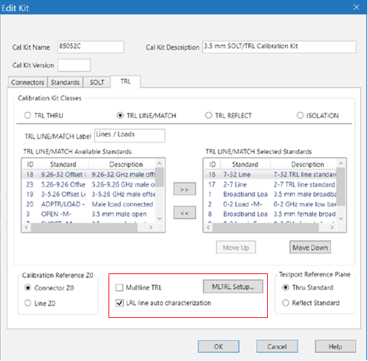
The dialog shown below is the TRL tab that comes up when editing the class definitions of the calibration kit. Its purpose is to define which standards are to be used during the TRL calibration. Both Legacy TRL or Multline TRL automatically use a Thru Reflect Match (TRM) calibration when the frequency is below the lowest start frequency of the LINE standards defined in the calibration kit if there are MATCH standards defined. The Multiline TSD algorithm differs from the Multiline TRL in how the algorithm uses the SHORT/REFLECT standard. The SHORT is assumed to be fully known and only connected to one port while the REFLECT only needs to be partially known but has to be connected to both ports; the LINE and DELAY standards are equivalent.
For TRL there are four categories of standards called Calibration Kit Classes. They are TRL THRU, TRL LINE/MATCH, TRL REFLECT and ISOLATION. The ISOLATION kit class is optional.
The TRL THRU kit class should be set up so that only a single standard is defined for a given set of port connectors.
Note: Generally this means that for Multiline TRL calibrations there will only be one standard defined in the TRL THRU kit class that is intended to be used over the entire frequency range. Sometimes users define calibration kits to cover multiple different port pairs; for example, if a calibration kit is created to support an on-wafer TRL calibration the user might define different ports that correspond to the topology of the set of probes that are used to touch down on the standards. The kit may have multiple pairs of ports. Giving each port a unique name allows the user to restrict which port pairs can be automatically set up to do a TRL calibration. In this case, you would have multiple THRU standards in the TRL THRU kit class. But only one of them would be used for a given TRL calibration between a pair of testports. It should be noted that the legacy TRL algorithm still may benefit from using multiple THRU standards in order to provide the best phase margin over different frequency ranges.
This actually represents two kit classes that share a similar purpose
during calibration. A LINE standard needs to have a distinct response
from the THRU standard. Typically the LINE standard is chosen
such that the phase of  is different from the phase
response of
is different from the phase
response of  by at least 20 degrees. This becomes
prohibitive at low frequencies so MATCH standards are used with
a TRM calibration at frequencies where it is impractical to create LINE
standards. Both the Legacy TRL and Multiline TRL calibrations use MATCH
standards and TRM calibration to cover the low frequency portion as needed.
In those cases, the calibration is actually a mix of TRM and TRL. The
TRM portion of the calibration is not over-determined when Multiline TRL
is selected. A fundamental assumption of the TRL algorithm is that the
characteristic impedance of the THRU standard is the same as the
characteristic impedance of each of the LINE standards. The match
standard can be defined as an idealized fixed load standard or it can
be defined as a databased standard which can be used to adjust for the
actual reflection coefficient of the standard. Both Legacy TRL and Multiline
TRL assume the databased standards have the same reflection coefficient
applied to both ports.
by at least 20 degrees. This becomes
prohibitive at low frequencies so MATCH standards are used with
a TRM calibration at frequencies where it is impractical to create LINE
standards. Both the Legacy TRL and Multiline TRL calibrations use MATCH
standards and TRM calibration to cover the low frequency portion as needed.
In those cases, the calibration is actually a mix of TRM and TRL. The
TRM portion of the calibration is not over-determined when Multiline TRL
is selected. A fundamental assumption of the TRL algorithm is that the
characteristic impedance of the THRU standard is the same as the
characteristic impedance of each of the LINE standards. The match
standard can be defined as an idealized fixed load standard or it can
be defined as a databased standard which can be used to adjust for the
actual reflection coefficient of the standard. Both Legacy TRL and Multiline
TRL assume the databased standards have the same reflection coefficient
applied to both ports.
Note: The NIST implementation does not permit having a calibration that mixes both TRM and TRL.
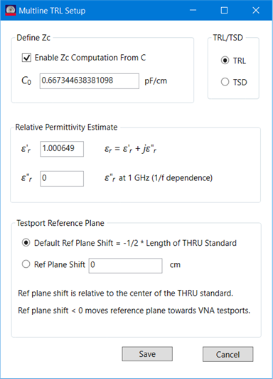
The TRL REFLECT kit class contains standards to be used by both the Legacy TRL and Multiline TRL calibrations. When doing a TRL calibration there is a fundamental assumption that the REFLECT standard is the same on both ports. It doesn’t have to be fully known, but should be approximately known to permit the correct root selection during the calibration process. A single reflect will be used, but most of the time multiple REFLECT standards need to be created one for each connector gender. The Multiline TRL algorithm has the option to do a TSD calibration instead of TRL calibration. In that case, only one reflect standard is required; but it has to be fully known. When doing a TSD calibration, one then has the option of deciding which reflect standard to be used. In general, the order of the calibration standards in a Calibration Kit Class is significant as the calibration algorithms step through the standards from top to bottom selecting standards until it accumulates enough standards to satisfy all of the frequency requirements for each port. In the case of TSD, the order of the REFLECT standards is significant because as the TSD portion of the algorithm steps through the standards listed in the TRL REFLECT kit class it will use the first REFLECT standard it finds that will mate with either of the test ports. The user specifies which algorithm to use Multiline TRL or Multiline TSD on a kit by kit basis by making the desired selection in the Multiline TRL Setup dialog as shown below.
A databased standard can be used for the reflect standard. In general there is no advantage to using a databased standard for Legacy TRL and Multiline TRL calibrations since only an approximate value for the reflect is required. There are a couple of instances where using a databased standard might provide benefit. In the Legacy TRL when the Reflect Standard is used to define the reference plane, the actual value of the reflect standard obtained from the stamndard model is used to set the reference planes. In the Multiline TSD calibration, the actual value of the standard model is also used to compute the error terms.
Legacy TRL and Multiline TRL do not support the use of databased standards for THRU or LINE standards. Databased standards can be used for MATCH or REFLECT standards.
The NIST MultiCal software defines the calibration standards using physical lengths and relative permittivity. The Keysight implementation also defines the same standards but uses an offset delay term to be consistent with existing calibration standard definitions[3]. Traditionally, the offset delay model used by both THRU and LINE standards has the offset defined by a delay parameter.
Note:The delay specified for the standard offset is assumed to be equivalent to the delay a TEM mode would face for a given physical length.
The Keysight Multiline TRL algorithm assumes the physical length is constant and computes that value from the offset delay parameter defined in the standard’s model. The physical length is obtained using the real part of the relative permittivity estimate (see Multiline TRL Setup dialog above) and then held constant even while the Multiline TRL algorithm adjusts the relative permittivity during subsequent computations.
Both Legacy TRL and Multiline TRL algorithms assume the characteristic
impedance for the THRU and LINE standards is the same. The
computations optimize the error terms for the characteristic impedance
of the standards. There are multiple impedance terms that are used by
both the Legacy TRL and Multiline TRL algorithms. There is an additional
impedance term  that is not defined in the calibration
kit but is computed by the TRL algorithms. It is inherently subject to
the assumptions that all of the THRU and LINE standards have the same
characteristic impedance. When Line Z0 is selected as the reference Z0 setting, the characteristic impedance of the measurement
system after calibration is simply .
that is not defined in the calibration
kit but is computed by the TRL algorithms. It is inherently subject to
the assumptions that all of the THRU and LINE standards have the same
characteristic impedance. When Line Z0 is selected as the reference Z0 setting, the characteristic impedance of the measurement
system after calibration is simply .
For Legacy TRL, when Connector Z0 is selected an impedance transformation
is applied which assumes that the Offset Z0
of the LINE standard is equal to
and the math to transform from Offset Z0
of the LINE standard to Z0 of the Connector
is applied. The following summarizes the effect of settings on the impedance
computations:
If the user selects Enable Zc
Computation From C then
is computed from C0 and  .
.
If the user unchecks Enable Zc
Computation From C then
is set equal to Offset Z0 of the
THRU standard.
Regardless of whether Enable Zc
Computation From C is checked or unchecked there is an
additional impedance transform from to Connector
Z0.
is set equal to Offset
Z0 of the THRU standard. There is no
additional impedance transform from to Connector
Z0. If the user selects Line Z0 in the Calibration Reference Z0 section of the TRL tab, the computed error terms are used without any additional impedance transform. Additionally, when the user selects Line Z0, the Define Zc section in the Multiline TRL Setup dialog is disabled.
There is a slight difference in behavior between Legacy TRL and Multiline TRL due to the additional Define Zc section in the Multiline TRL Setup dialog.
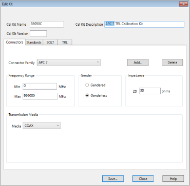
Legacy TRL uses the definition of Offset Z0 and Offset Loss specified in the LINE standard model. If this is not equal to the Connector Z0 specified on the Connectors tab (shown below) an impedance transform is applied to the error terms.
Multiline TRL uses the definition of Offset Z0 specified in the THRU standard model. If Enable Zc computation from C is checked in the Multiline TRL Setup dialog an additional impedance transform is done to account for the low frequency dispersion specified by C0.
Note: There are papers published to explain details for determining the low frequency dispersion from the characterization of the propagation constant and an estimate of C0[4][5][6]. This also uses the characterization of the relative permittivity which covers the full frequency range of the Multiline TRL algorithm. The transmission line capacitance can also be characterized by additional measurements[7]
If the Offset Z0 specified in the THRU standard model is different from the Connector Z0 specified on the Connectors tab the error terms are modified by an impedance transform. A default value for C0 is computed assuming a coaxial transmission structure using characteristic impedance specified by Offset Z0 for the THRU standard model. Inputting a negative value for C0 will cause the default value to be reinserted.
Note: There is also an interaction between er’ and C0. If C0 is equal to the default value changes to er’ will update C0. If a user has specified a different value for C0 no change to C0 will be made when changes to er’ are made.
The testport reference plane options differ between the Legacy TRL and Multiline TRL options. The initial calibrations for both Legacy TRL and Multiline TRL both assume the reference plane is in the middle of the THRU standard. This becomes significant for the LRL case where the delay of the THRU standard is greater than zero.
Legacy TRL has the option to use either the THRU standard or the REFLECT standard to set the reference plane after calibration. If the THRU standard is selected the reference plane for each testport will be rotated towards the VNA testport by half the delay of the THRU standard. If LRL line auto characterization is checked, the propagation constant computed during the TRL calibration will be used to estimate the rotation based on the delays specified by the THRU and LINE standards; otherwise, the modeled behavior of the THRU standard will be used.
When Multiline TRL is selected the ability to select LRL line auto characterization is disabled because Multiline TRL only uses LRL line auto characterization. The ability to select the REFLECT standard to be used to define the testport is not an option with Multiline TRL; however, there is an additional option of defining an arbitrary reference plane. A negative number input for the reference plane shifts the testport towards the VNA testports.
The default behavior is to shift the testport reference plane to the edge of the THRU standard like with behavior similar to the Legacy TRL behavior with the testport reference plane set by the THRU standard and having LRL line auto characterization active.
The diagnostic traces are available in the Cal Set viewer. The trace also shows the transition between the portion of the frequency range that did a TRM calibration and the portion that did a Multiline TRL calibration.
Multline TRL has diagnostic traces that provide insight into the calibration as shown below.
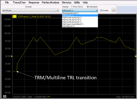
The traces are the same as traces provided by the NIST MultiCal software. These traces can be accessed from the Cal Set Viewer under the Standards group.
Note: The default format for viewing the traces is log magnitude. The diagnostic traces make the most sense when viewed in real or imaginary format. The indicated units for each diagnostic trace is simply a number (U); when looking at the various diagnostic traces the screen doesn’t include units such as degrees or ohms.
The included diagnostic traces are:
 ) given as
 where
where  is
the real part and
is
the real part and  is the
imaginary part. Strictly speaking, this is not the mean of each of
the RelPermittivityPair(n); pairs of
lines with the best effective phase delay have influence. ) between the THRU
and multiple LINE standards paired with the THRU or
LINE standard that has the best effective phase difference
with the rest of the THRU and/or LINE standards. These
are the terms that are combined to give the estimate of RelPermittivityMean.
The number of pairs is equal to the number of LINE standards.
is the
imaginary part. Strictly speaking, this is not the mean of each of
the RelPermittivityPair(n); pairs of
lines with the best effective phase delay have influence. ) between the THRU
and multiple LINE standards paired with the THRU or
LINE standard that has the best effective phase difference
with the rest of the THRU and/or LINE standards. These
are the terms that are combined to give the estimate of RelPermittivityMean.
The number of pairs is equal to the number of LINE standards. where
where  is the attenuation
constant and
is the attenuation
constant and  is the phase constant. The transmission
through a line of length l in cm is given
as
is the phase constant. The transmission
through a line of length l in cm is given
as  and
the imaginary part of RelPhaseConst&Atten represents
and
the imaginary part of RelPhaseConst&Atten represents  expressed in dB where c is the speed of light in a vacuum and
fGHz is the frequency in GHz.
expressed in dB where c is the speed of light in a vacuum and
fGHz is the frequency in GHz. The diagnostic traces only have a non-zero value in the frequency range where the Multline TRL algorithm is used. The transition between TRM and Multiline TRL is seen in the diagnostic trace above.
The following steps are recommended when creating a new calibration kit to be used with Multiport TRL calibrations.
Note: This is not a fixed requirement when the calibration kit is used for multiport calibrations (more than 2 testports); what is required is that all connectors used to define the standards for a Multiline TRL calibration (or Legacy TRL calibration) must have the same characteristic impedance. For example, consider the case where TRL calibrations are intended between ports A and B and between ports C and D. Assume Probe A is intended to be connected to port A, Probe B to port B, Probe C to port C and Probe D to port D; the characteristic impedance defined for Probe A must be the same as Probe B and the characteristic impedance defined for Probe C must be the same as Probe D but the characteristic impedance defined for Probe A can be different than the characteristic impedance defined for Probe C.
)
that will be defined on the Multiline TRL Setup dialog. The delay
in picoseconds (psec) for the
ith
standard with length Li in cm
is computed as  where
where  .
.Note: In the case where multiple TRL sets of calibration standards are defined, there should be a single THRU standard for each set. Using the previous example, there would be a THRU defined with Probe A and Probe B connectors and another THRU defined with Probe C and Probe D connectors.
[1] |
R. B. Marks, “A multiline method of network analyzer calibration,” IEEE Transactions on Microwave Theory and Techniques, vol. 39, no. 7, pp. 1205–1215, 1991. |
[2] |
D. C. DeGroot, J. A. Jargon, and R. B. Marks, “Multiline TRL revealed,” in 60th ARFTG Conference Digest, Fall 2002., pp. 131–155. |
[3] |
Keysight Technologies, Specifying Calibration Standards and Kits for Keysight Vector Network Analyzers, Dec. 2019. [Online]. Available: https://www.keysight.com. |
[4] |
D. F. Williams, U. Arz, and H. Grabinski, “Characteristic-impedance measurement error on lossy substrates,” IEEE Microwave and Wireless Components Letters, vol. 11, no. 7, pp. 299–301, 2001. |
[5] |
R. B. Marks and D. F. Williams, “Characteristic impedance determination using propagation constant measurement,” IEEE Microwave and Guided Wave Letters, vol. 1, no. 6, pp. 141–143, 1991. |
[6] |
D. F. Williams and R. B. Marks, “On-wafer impedance measurement
on lossy substrates,” IEEE Microwave and Guided Wave Letters,
vol. 4, no. 6, pp. 175–176, |
[7] |
“Transmission line capacitance measurement,” IEEE Microwave and Guided Wave Letters, vol. 1, no. 9, pp. 243–245, 1991. |