Parameters
Description
Vector
-
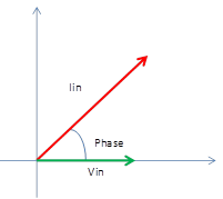
Iin (Arms)
-
Iin (Apeak)
-
Current of input
-
Vector value
-
The reference of Phase is Vin
-
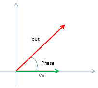
Iout (Arms)
-
Iout (Apeak)
-
Current of output
-
Vector value
-
The reference of Phase is Vin
-
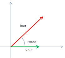
Iout (Relative to Vout Phase)(Arms)
-
Iout (Relative to Vout Phase)(Apeak)
-
Current of output
-
Vector value
-
The reference of Phase is Vout
-
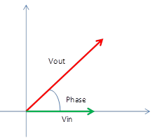
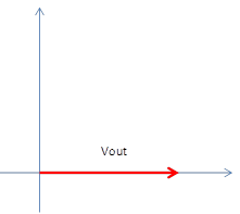
Vout (Vrms)
-
Vout (Vpeak)
-
Voltage of output
-
Vector value
-
The reference of Phase is Vin
-
Vout(Zero Phase)(Vrms)
-
Vout(Zero Phase)(Vpeak)
-
Absolute Voltage of output
-
Vector value
-
Phase is 0
-
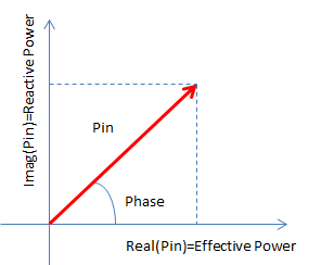
Pin
-
Power consumed at input
-
Pin=conj[Vin(Vrms)]× Iin(Arms), conj[Vin(Vrms)] is a complex conjugate
-
Vin, Iin, Pin are vector values.
-
You can display the following parameters by selecting format.
-
Lin Mag: Apparent Power [VA: volt-ampere]
-
Real: Effective Power [W: watt]
-
Imag: Reactive Power [Var: volt-ampere reactive]
-
Pout
-
Power consumed at output
-
Pin=conj[Vout(Vrms)]× Iout(Arms), conj[Vout(Vrms)] is a complex conjugate
-
Vout, Iout, Pout are vector values.
-
You can display the following parameters by selecting format.
-
Lin Mag: Apparent Power [VA: volt-ampere]
-
Real: Effective Power [W: watt]
-
Imag: Reactive Power [Var: volt-ampere reactive]

-
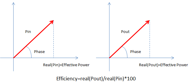
Efficiency(real(Pout)/real(Pin))(%)
-
Ratio of real part of output and input power in percent
-
Result is vector value but imaginary part is always 0.
-
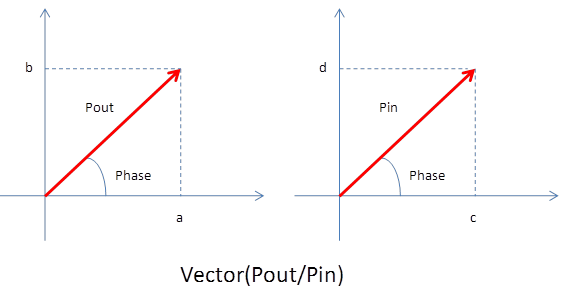
Vector(Pout/Pin)
-
Pout/Pin in vector value
-
where Pout=a+jb、Pin=c+jd,
Vector(Pout/Pin)=(a+jb)/(c+jd)=(ac+bd)/(c2+d2)+j(bc-ad)/(c2+d2)
-
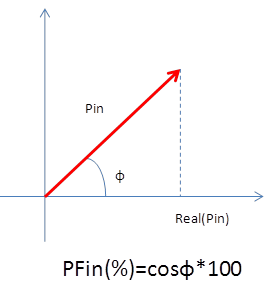
PFin (%)
-
Power factor at input power in percent
-
where phase of Pin is Φ,
PFin(%)=cosΦ×100 -
Result is vector value but imaginary part is always 0.
-
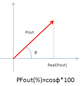
PFout (%)
-
Power factor at outout power in percent
-
where phase of Pout is Φ,
PFout(%)=cosΦ×100 -
Result is vector value but imaginary part is always 0.
-
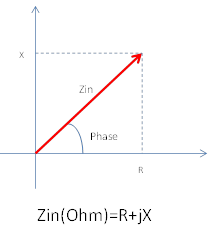
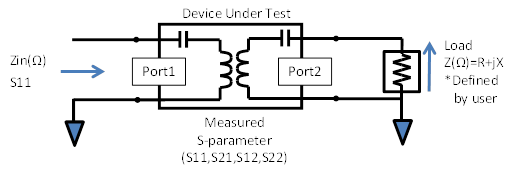
Zin (Ω)
-
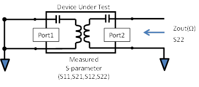
Impedance of port 1 when Port2 is terminated with R+jX
-
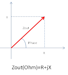
Zout (Ω)
-
Impedance of port 2 when Port1 is terminated with 0Ω
-
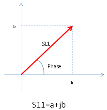
S11
-
Reflection S11 of port 1 when Port2 is terminated with R+jX
-
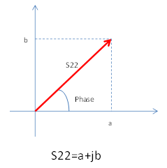
S22
-
Reflection S22 of port 2 when Port1 is terminated with 0Ω
RCE
Optimum resonator coupling efficiency representing maximum power transfer efficiency between transmitting and receiving resonators.
N/A
RCE (%)
Display RCE in percentage.
N/A
Z21 (Imag) (Ω)
Imaginary component of open circuit forward transfer impedance defined in the Z-parameter matrix for the two-port network.
N/A