This section describes how to measure a Capacitor. In this example, apart from E5061B option 005, 16201A terminal adapter and 16196A test fixture are used. The measurement is performed with 10 pF capacitor, hence, to measure another device under test (DUT), change the measurement conditions to suit accordingly. Prior to the measurement, ensure that the 16201A terminal adapter is connected to the E5061B network analyzer. See Connecting Terminal Adapter.
Set the trace display settings.
Display > Num of Traces > 2
Display > Allocate Traces > x2
Set the measurement port to S-Parameter.
Meas > Measurement Port > S-Parameter
Set the measurement method to Port 1 Reflection.
Meas > Impedance Analysis Menu > Method > Port 1 Refl
Set the measurement type of each trace.
Select Trace 1 as the active trace. Meas > Impedance Analysis Menu > |Z|
Select Trace 2 as the active trace. Meas > Impedance Analysis Menu > qz
Set the format of the measurement of each trace.
Select Trace 1 as the active trace. Format > Exp Phase > OFF
Select Trace 2 as the active trace. Format > Exp Phase > OFF
Set the sweep setup power.
Sweep Setup > Power > -10dBm
Set the sweep type.
Sweep Setup > Sweep Type > Log Freq
Set the frequency bandwidth.
Avg > IF Bandwidth > 100 Hz
Once the measurement condition is set, impedance calibration should be performed. The 16195B calibration kit is required to perform the calibration.
Connect the E4991-60022 OPEN standard to the 16201A terminal adapter (which is connected to Port 1 of E5061B).
Cal > Cal Kit > 16195B
Cal > Calibrate > Impedance Calibration > Open
Once the open calibration is completed, a checkmark ![]() is displayed to the left of the Open menu.
is displayed to the left of the Open menu.
Remove the OPEN standard and connect the E4991-60021 SHORT standard to the terminal adapter.
Cal > Calibrate > Impedance Calibration > Short
Once the short calibration is completed, a checkmark ![]() is displayed to the left of the Short menu.
is displayed to the left of the Short menu.
In the same way, measure the calibration data for LOAD standard and LOW LOSS C standard. Use 04287-60021 50 W termination LOAD standard and 04287-60022 LOW LOSS Capacitor standard.
Cal > Calibrate > Impedance Calibration > Load
Cal > Calibrate > Impedance Calibration > Low-Loss C
Once the calibrations are completed, a checkmark ![]() is displayed to the left of the Load and Low-Loss C menu.
is displayed to the left of the Load and Low-Loss C menu.
Set the calibration to DONE to save the performed calibration.
As 16196A test fixture is used in this measurement example, fixture compensation should be performed to reduce possible errors induced by the test fixture. Ensure that the insulator assembly used is appropriate with the DUT. Refer to 16196A Test Fixture Operation and Service Manual to learn more about the fixture.
Select Trace 1 as the active trace. Scale > Y-Axis > Log
Scale > Auto Scale All
This section describes how to use Equivalent Circuit function to analyze the measurement.
Analysis > Equivalent Circuit > Select Circuit > D.
Analysis > Equivalent Circuit > Calculate. The calculated equivalent circuit parameters are displayed in each box of R1, C1 and L1.
Analysis > Equivalent Circuit > Simulate > ON.
Analysis > Equivalent Circuit > Display > ON.
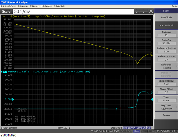
Sample results as shown below:
DUT: 10 pF capacitor
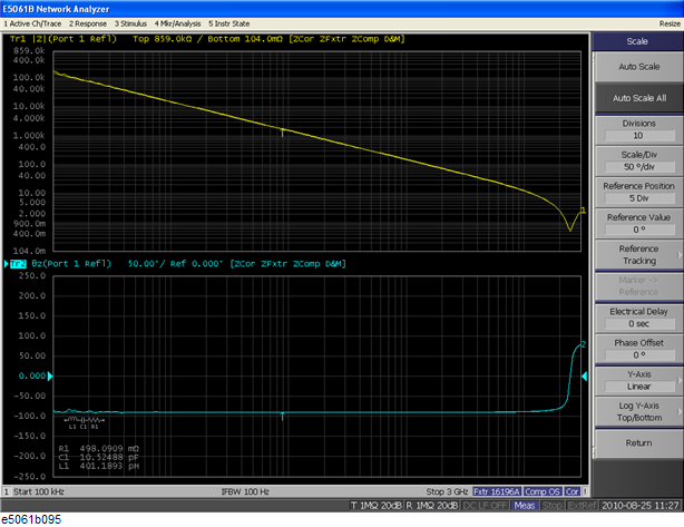
DUT: 100 pF capacitor