Other topics about Fixture Simulator
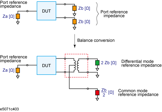
By using the port impedance conversion function, you can specify the impedance of each test port. As a result of this conversion, the impedance of the balanced port in differential mode is set to a value twice as large as the impedance of the two unbalanced ports before conversion, and in common mode to a value one-half as large.
Be sure to set the impedances of the two unbalanced ports equal to each other. For more details on setting up port impedance for unbalanced ports, refer to Converting the Port Impedance of the Measurement Result.
Port impedance after a balance-unbalance conversion

As described above, the impedance of the balanced port is automatically specified as the result of specifying the impedance of the two unbalanced ports prior to balance-unbalance conversion. However, the port impedance can be changed to an arbitrary value by using the differential port impedance conversion function and the common port impedance conversion function.
If you turn on the differential port impedance conversion function, the port reference impedance in the differential mode is converted to an arbitrary value specified with this function instead of the value in the above figure.
Press Analysis > Fixture Simulator > Diff ZConversion.
Click Diff ZConversion > ON.
You can only turn on or off Differential Port Impedance Conversion for all of the balanced ports together, not for each port individually. If you want to turn off only a specific port, set the reference impedance of the port to the value in the above figure.
Press Analysis > Fixture Simulator > Diff ZConversion.
Click Port 1 (bal) Real to specify the port reference impedance in "Real" format for differential mode.
Click Port 1 (bal) Real and Port 1 (bal) Imag to set the differential port reference impedance in "Complex" format.
If you turn on the common port impedance conversion function, the port reference impedance in the common mode is converted to an arbitrary value specified with this function instead of the value the above figure.
Press Analysis > Fixture Simulator > Cmn ZConversion.
Click Cmn ZConversion > ON.
You can only turn on or off Common Port Impedance Conversion for all of the ports together, not for each port individually. If you want to turn off only a specific port, set the impedance of the port to the value in the above figure
Press Analysis > Fixture Simulator > Cmn Z Conversion.
Click Port 1 (bal) Real to specify the port reference impedance in "Real" format for common mode.
Click Port 1 (bal) Real and Port 1 (bal) Imag to set the common port reference impedance in "Complex" format.