Other topics about Fixture Simulator
The Fixture Simulator is a function that uses software in the E5063A to simulate various measurement conditions based on the measurement results. The functions available in Fixture Simulator are as follows:
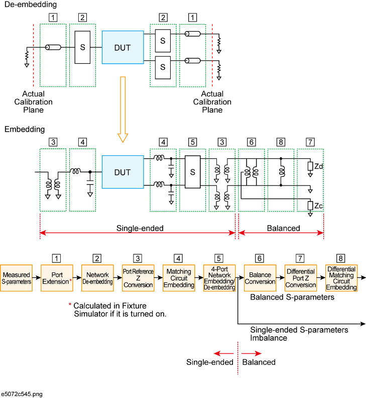
Data processing flow diagram of fixture simulator
Port extension is an independent function from the fixture simulator, but if the fixture simulator function is on, data processing is automatically executed as a function of the fixture simulator to improve the data processing efficiency. (Measurement result is the same as when the fixture simulator is turned off.) Port extension moves the calibration reference location by setting an electrical delay for a single-ended port. Port extension can eliminate only electrical delay (phase shift) for each single-ended port. Loss or mismatch cannot be eliminated by this function.
The following three functions are applied to single-ended ports (unbalanced ports). Balance-unbalance conversion can additionally be applied to single-ended ports.
A function that uses software to remove an arbitrary network (50 Ω system) defined by a two-port Touchstone data file from each test port (single-ended) and to extend the calibration plane. This makes it possible to remove networks that create error elements between the calibration plane and the DUT, thereby enabling a more realistic evaluation of the DUT.
For the setup procedure of the network de-embedding function, see Extending the Calibration Plane Using Network De-embedding.
A function that uses software to convert an S-parameter measured with a 50 Ω port reference impedance into a value measured with an arbitrary impedance.
For the setup procedure of port reference impedance conversion, see Converting the Port Impedance of the Measurement Result.
A function for converting an original measurement result into a characteristic determined under the condition of inserting a matching circuit between the DUT and the test port (single-ended). The matching circuit to be inserted is either selected from the five predetermined circuit models or provided by a designated arbitrary circuit defined in a two-port Touchstone file.
For the setup procedure used for matching circuit embedding, see Determining Characteristics After Adding a Matching Circuit.