Other topics about Setting Up Test Sequence
The display of Edit Menu depends on the security mode. In Administrator Security Mode, password is required to enter the Edit Test and perform changes.
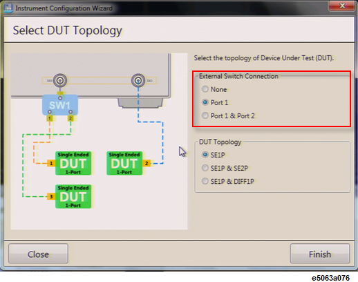
To select the DUT Topology:
Click Edit Test at Home menu.
Click Modify at Edit Test page.
Instrument Configuration Wizard is executed and Select DUT Topology dialog box appears.
Define the external switch connection setup (U1810B switch) as well as DUT topology, click on the option matching the physical connection and click Finish.
Test Wizard can connect up to 4 ports when you use U1810B switch. However, you can make only 2 port-measurement at any one time.
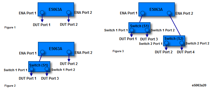
You can connect up to 2 switches to E5063A,which means you may make, up to 4 DUT port measurement. When you connect only one switch, you must connect it to port 1 of the E5063A.
If the number of connected U1810B switch is set at 2 but only 1 switch is connected:
In Edit menu: Warning message pops up.
In Executed Test menu: Error message pops up.
To learn more about U18010B USB Coaxial Switch SPDT, visit www.keysight.com.
In the Test Wizard, DUT port number is assigned to physical DUT port number is used for control purpose.
Correlation of number of switch with the maximum number of ports is shown in the below table:
DUT port number assignment
|
Figure # |
No. of U1810B switches |
Maximum no. of DUT ports |
DUT Port 1 |
DUT Port 2 |
DUT Port 3 |
DUT Port 4 |
|
1 |
0 |
2 |
E5063A Port 1 |
E5063A Port 2 |
N/A |
N/A |
|
2 |
1 |
3 |
U1810B Port 1 |
E5063A Port 2 |
U1810B Port 2 |
N/A |
|
3 |
2 |
4 |
U1810B Switch 1 Port 1 |
U1810B Switch 2 Port 1 |
U1810B Switch 1 Port 2 |
U1810B Switch 2 Port 2 |
Typical Configuration and DUT Topology
|
Number of your DUTs |
Required Number of USB Switch |
Port Connection (DUT Port Number: Px) |
||||
|
Single-end 1-Port DUT |
Single-end 2-Port DUT |
Differential 1-Port DUT (Physical 2 Port) |
Single-end 1-Port DUT |
Single-end 2-Port DUT |
Differential 1-Port DUT |
|
|
1 |
0 |
0 |
0 |
P1 or P2 |
- |
- |
|
1 |
1 |
0 |
1 |
P3 |
P1-P2 |
- |
|
1 |
0 |
1 |
1 |
P3 |
- |
P1-P2 |
|
2 |
0 |
0 |
0 |
P1,P2 |
- |
- |
|
2 |
1 |
0 |
2 |
P3 |
P1-P2 |
- |
|
2 |
0 |
1 |
2 |
P3,P4 |
- |
P1-P2 |
|
3 |
0 |
0 |
1 |
P1,P2,P3 |
- |
- |
|
4 |
0 |
0 |
2 |
P1,P2,P3, P4 |
- |
- |
|
0 |
1 |
0 |
0 |
- |
P1-P2 |
- |
|
0 |
0 |
1 |
0 |
- |
- |
P1-P2 |
|
0 |
2 |
0 |
2 |
- |
P1-P2, P3-P4 |
- |
|
0 |
0 |
2 |
2 |
- |
- |
P1-P2, P3-P4 |
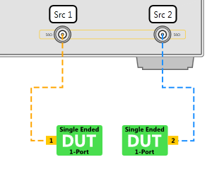
Single Ended 1-Port Topology with no Switch connected
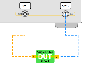
Single Ended 2-Port Topology with no Switch connected
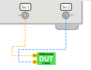
Differential 1 Port Topology with no Switch connected
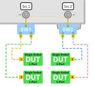
Single Ended 1-Port Topology with 1 Switch
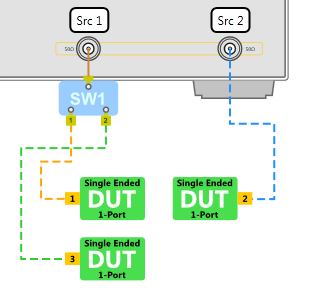
Single Ended 1-Port and Single Ended 2-Port Topology with 1 Switch
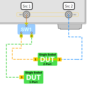
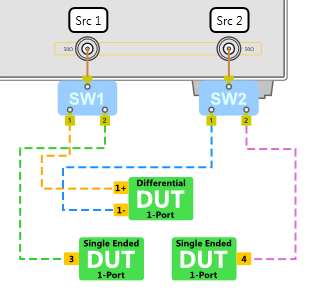
Single Ended 1-Port and Differential 1-Port Topology with 1 Switch

Single Ended 1-Port Topology with 2 Switches
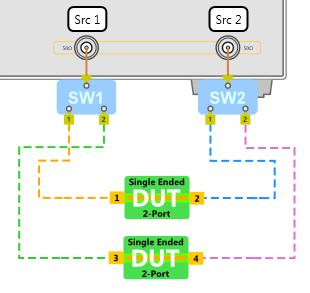
Single Ended 2-Port Topology with 2 Switches
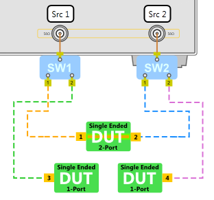
Single Ended 1-Port and Single Ended 2-Port Topology with 2 Switches
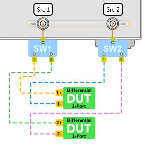
Differential Single Ended 1-Port with 2 Switches
Single Ended 1-Port & Differential 1-Port Topology with 2 Switches
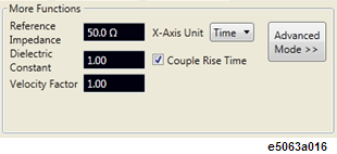
Reference Impedance
Editing dielectric constant changes the value of velocity factor automatically.
Related to dielectric constant, hence, editing dielectric constant automatically changes the value of velocity factor and vise versa.
The unit of X-axis. Selection choices are Second, Meters or Inches.
Couples the rise time between test items.
Activates the advanced mode, where the E5063A softkey menu are activated.
In the Advanced Mode, you can access all setting of E5063A. The setting you changed may affect the measurement unexpectedly. The measurement may not be correct if you have such a case. Therefore, the measurement performance is not guaranteed in the Advanced Mode.
It is known that changing the following setting causes incorrect measurement.
|
Hard key |
Do not use |
|
Meas |
Do not change the parameter |
|
Sweep Setup |
Start/Stop/Center/Span Points Sweep Type |
|
Marker Function |
Marker -> Start, Marker -> Stop |
Here is another caution in the Advanced Mode.
|
Function |
Note |
|
|
Display |
Increasing Num of Trace |
This may cause to tilt the wave form in the time domain. |
|
Analysis |
Fixture Simulator |
This may cause to tilt the wave form in the time domain. |
|
Transform > Window > Impulse width |
This may cause the setting change. |
|
|
Calibration |
Increasing Port Extension |
This may cause to exceed the DUT length limitation. |
|
Scale |
Increasing Electrical Delay |
This may cause to exceed the DUT length limitation. |
|
Ave |
IF Bandwidth |
Even if you have narrow IF Bandwidth, you may not have noise reduction at lower frequency. |
|
Display |
Data Math, Equation Editor |
The data and memory positions in data processing are different. |
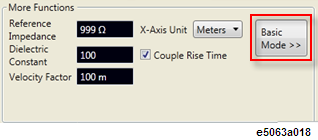
To configure more functions:
Click Edit Test at Home menu.
List of functions are found under More Functions group. Enter or select the desired value:
Reference impedance - by default its set to 50 W.
Dielectric constant & Velocity Factor - when you change the dielectric constant, the velocity factor is changed automatically according to the below formula. This value is used to convert from electrical length to physical length at X-Axis and Marker reading:
Velocity Factor = 1/sqrt(Dielectric Constant)
X-Axis Unit - can be toggled between time and length. Length can be defined in meters or inches.
Couple Rise Time - check this option to couple Rise Time between test items.
Advanced Mode -
Click on this button and below dialog box appears.
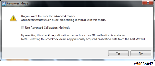
When you want to perform any calibration such as 8 term-calibration in Advanced Mode, select the check box named Use Advanced Calibration Methods in dialog box.
In advance calibration methods:
Deskew and DLC can not be used because its accuracy becomes worse.
The calibration you did in basic mode is cleared.
Click Yes to start the Advanced Mode.
The following settings are changed.
Softkeys are displayed on the right side of screen.
All hard keys are unlocked.
SVC in the instrument status bar turns in blue.
Once Advanced Mode is activated, the button is replaced by Basic Mode button as shown below. Click on the this button to return to normal mode, which presets the firmware.