Other topics about Mixer Calibration
The E5071C has a scalar-mixer calibration function for measuring frequency conversion devices.
Scalar-mixer calibration allows you to measure the magnitude value and reflection parameter of the mixer's conversion loss with very high accuracy by performing calibration using calibration standards (OPEN/SHORT/LOAD) in combination as well as a power meter.
For measurement of the conversion loss in a frequency conversion device, normal full 2-port calibration is not available because of the frequency difference between the stimulus port and the response port. Therefore, scalar-mixer calibration allows you to correct the error term that resides in a full 2-port error model by using the error model and an expression based on a new concept.
You can correct the following error elements by using the scalar-mixer calibration.
The reflection between the output port of the network analyzer and the input port of the measured mixer (vector error correction).
The reflection between the output port of the measured mixer and the input port of the network analyzer (vector error correction).
Transmission frequency characteristics at different frequencies (scalar error correction).
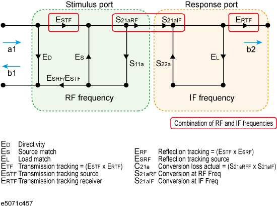
The frequency-offset error model can be described by the flow graph in the figure below. From the flow graph it can be seen that the model is divided in two halves: the stimulus port and the response port. By conceptualizing the error model in these two halves, each error term can be isolated to either of the model's halves depending on the frequency at which it was generated. The majority of the signals will only affect measurements by causing errors at the same frequency.
Two error signals that are functions of both halves of the frequency-offset model are isolation (EXF) and transmission tracking (ETF). EXF is set to zero because it is cannot be detected by the frequency change. ETF must be divided into two types of errors: one associated with the stimulus side at the input frequencies and the other associated with the response side at the output frequencies. As previously discussed, calculating the transmission tracking (ETF) based on both stimulus and response sides is the key to using error correction during frequency-offset measurements.

In scalar-mixer calibration, use the power meter to measure the transmission tracking error (ESTF) of the signal source in both the output and input frequencies in order to calculate the transmission tracking in the frequency-offset (ETF). The transmission tracking of the receiver in the output frequency (ERTF) can be determined by dividing the transmission tracking (ETF) calculated based on the output frequency in full 2-port calibration by the receiver's transmission tracking (ESTF). Multiplying the signal source transmission tracking (ESTF) by the receiver transmission tracking (ERTF) provides the transmission tracking in the frequency-offset (ETF). Since ESTF and ERTF are products of two power measurements, the resulting correction coefficient is a scalar parameter.
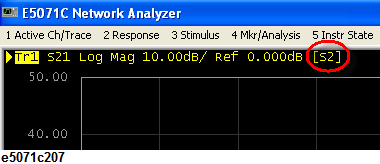
You can confirm the progress of error correction for each channel by viewing the error calibration status. For the traces in which the scalar-mixer is valid, the status [S2] is added.

In scalar-mixer calibration, the normal calibration coefficient is invalid while the frequency-offset sweep is in progress; in this case the scalar-mixer calibration coefficient is used instead. Turning the frequency-offset sweep off switches over to the normal calibration coefficient; however, the information on the scalar-mixer calibration coefficient is retained.
Before starting scalar-mixer calibration, verify that the frequency-offset is activated by clicking Sweep Setup key > Frequency Offset. If the frequency-offset is not valid, you cannot start scalar-mixer calibration.
Press Channel Next/Channel Prev keys to select the channel you want to calibrate.
Press Cal key.
Click Mixer/Converter Calibration > Scalar Cal (Manual) > Select Ports.
Select the test port for starting scalar-mixer calibration.

For the scalar-mixer calibration, only one direction with 2-ports calibration is available. "One direction" means the forward or reverse direction. Two directions may be used among the same ports, but this would not be full 2-port scalar-mixer calibration but simply the simultaneous operation of single-direction scalar-mixer calibrations.. .
Both x and y in the following steps are provided for the case where you have selected in the test port selection.
Click Reflection.
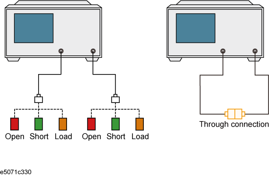
Connect the OPEN calibration standard to the test port x (connector for the DUT).
Click Port x @Freq x Open to start measurement of the calibration standard.
Click Port x @Freq y Open to start measurement of the calibration standard.
Disconnect the OPEN calibration standard, then connect SHORT calibration standard in its place.
Click Port x@Freq x Short to start measurement of the calibration standard.
Click Port x@Freq y Short to start measurement of the calibration standard.
Disconnect the SHORT calibration standard, then connect LOAD calibration standard in its place.
Click Port x@Freq x Load to start measurement of the calibration standard.
Click Port x@Freq y Load to start measurement of the calibration standard.
Repeat the procedure for port y.
Click Return.
Click Transmission.
Connect a THRU between the test ports x and y (between the connectors for the DUT).
Click Port y-x@Freq y Thru to start measurement of the calibration standard.
Click Port x-y@Freq x Thru to start measurement of the calibration standard.
Click Return.
Click Power Meter. See Preparing to control the power meter for setup the power meter.
Click Use Sensor. Each time the key is pressed, Channels A and B switch over alternately. If you are using a one-channel power meter, select Channel A.
Connect the power sensor for the selected channel to the selected port.
Click Port x@Freq x.
Click Port x@Freq y.
Click Port y@Freq x.
Click Port y@Freq y.
Click Return.
Click Done to exit the scalar-mixer calibration. This step allows the calibration coefficient to be calculated, turning on the error correction function automatically.
Before starting scalar-mixer calibration, verify that the frequency-offset is activated by clicking Sweep Setup key > Frequency Offset. If the frequency-offset is not valid, you cannot start scalar-mixer calibration.
Press Channel Next/Channel Prev keys to select the channel you want to calibrate.
Press Cal key.
Click Mixer/Converter Calibration > Scalar Cal (ECal) > Select Ports.
Select the test port for starting scalar-mixer calibration.
Click Power Meter. See Preparing to control the power meter for setup the power meter.
Click Use Sensor. Each time the key is pressed, Channels A and B switch over alternately. If you are using a one-channel power meter, select Channel A.
Connect the power sensor for the selected channel to the selected port.
Click Port x@Freq x.
Click Port x@Freq y.
Click Port y@Freq x.
Click Port y@Freq y.
Click Return.
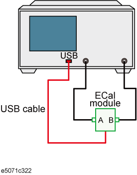
Connect the test port you selected to the ECal module.

Click ECal & Done. The calibration coefficient will be calculated, turning on the error correction function automatically.
If the ECal module is not connected to the E5071C or power calibration have not been done yet, the ECal & Done menu item will not be not available. In addition, if the ECal module is not connected to the test port of the calibration target, an error may occur.