Other topics about Fixture Simulator
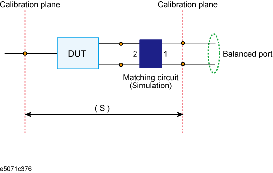
You can obtain the characteristics resulting from the pseudo addition of a balance matching circuit to a balanced port created by balance-unbalance conversion. By using the matching circuit function, you can obtain the characteristics resulting from the addition of an arbitrary matching circuit for each test port.
Balance matching circuit function

The balance matching circuit (Differential matching circuit embedding) is not applied to single-ended S-parameter results. For example, the balance matching circuit is not applied to the imbalance parameter as it is derived from single-ended S-parameters.
Define the matching circuit to be added by one of the following methods:
Use a predetermined circuit model and specify the values for the elements in the circuit model.
Use a user file (in two-port Touchstone format) to define the matching circuit to be added.
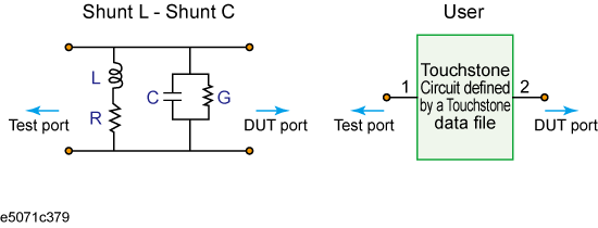
The following figure shows the circuit models used in defining a balance matching circuit.
Circuit models used to define balance matching circuit

For a network defined in a user file, it is assumed that port 1 is connected to the test port and port 2 is connected to the DUT.
The setup steps are shown below.
Press Analysis key, then click Fixture Simulator > Diff. Matching.
Click Select Port.
Click 1, 2, or 3 to select the port on the DUT to which a differential matching circuit will be added.
To add a matching circuit defined in a user file, perform the following operations:
Press User File.
Using the dialog box that appears, select the 2-port Touchstone data file (.s2p format) for the matching circuit to be added.
Once you have specified the user file, the selection of Select Circuit automatically changes to User. In this case, you do not have to execute Step 5 and Step 6.
Click Select Circuit.
Select a differential matching circuit model.
|
Softkey |
Function |
|
None |
The matching circuit is not added. |
|
Shunt L - Shunt C |
Selects a circuit model consisting of a shunt inductor and a shunt capacitor |
|
User |
Selects the circuit model defined in the user file imported in Step4. |
Specify the values for the elements in the circuit model selected.
|
Softkey |
Function |
|
C |
Specifies the capacitance [F] |
|
G |
Specifies the conductance [S] |
|
L |
Specifies the inductance [H] |
|
R |
Specifies the resistance [Ω] |
When either of the two components of Shunt-L, "L" and "R", is set to 0, the component is defined as "Short"; when both components are set to 0, they are defined as "Open."
Repeat the procedure to set up the differential matching circuit to be added to the selected ports on the DUT.
Click Diff. Matching to turn the differential matching circuit ON.
Click Return.
If Fixture Simulator is OFF, press the key again to turn it ON.