Other topics about Making Measurement
In the low-latency external trigger mode, variations in delay time between the reception of a trigger and the start of a one-point measurement are decreased for point trigger measurement by using trigger pulses supplied to the external trigger input terminal. In addition, using this mode will allow you to decrease the variations in the time required to be ready for the next measurement trigger after execution of a one-point measurement. This mode allows you to perform continuous point trigger measurement in sync with external trigger pulses and accurately set a trigger delay time at each point-trigger point.
The time required for measurement at each measurement point varies depending on the settings of the E5071C and the type of measurement. For more information, see External trigger delay time and point trigger interval.
The low-latency external trigger mode becomes available by turning on the point trigger function and setting the trigger source to "External."
|
Low-latency external trigger mode |
Function |
|
ON |
Sets the low-latency external trigger mode to ON. The external trigger delay time becomes valid. |
|
OFF |
Sets the low-latency external trigger mode to OFF. |
If the trigger source is not the external trigger, the low-latency external trigger mode does not work if it is specified to ON.
The setting of the low-latency external trigger mode is valid for all channels.
If the trigger source is set to "External" and the trigger event to "On" (On Point), set the low-latency external trigger mode.
Press Trigger key.
Click Low Latency.
Click ON to activate the-low latency external trigger mode.
Set the external trigger delay time at each point. The setting resolution is 10 µs.
Press Trigger key.
Click Trig Delay.
Enter an external trigger delay time.
External trigger pulses, supplied until the next measurement becomes ready after the start of a one-point measurement, are ignored, and the next trigger is generated by a pulse supplied after the completion of the one-point measurement.
The time until the next trigger can be accepted after the start of a one-point measurement depends on the IFBW and other settings of the analyzer. For example, in the case of a frequency's zero-span measurement, the time until the next measurement is ready after the start of a one-point measurement is obtained by dividing the time required for a single sweep in On Sweep mode, instead of On Point mode, by the number of measurement points. If you use the point trigger function with external trigger pulses that are wider than this time, point trigger measurement is performed at each pulse input.
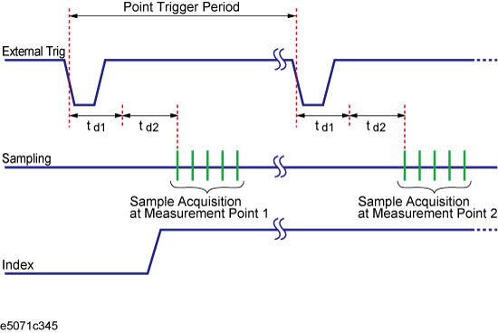
The figure below shows the timing chart of an external trigger when the point trigger function is on.
Timing chart of external trigger (trigger event = on, trigger source = external, low-latency external trigger mode = on)

The table below describes signals and time as shown in the above figure.
|
Signal, time |
Description |
|
External Trig |
External trigger signal to be supplied. |
|
Sampling |
Time while the E5071C is actually performing measurement. |
|
Index |
/Index signal of the handler I/O port. When the point trigger function is ON and the low-latency external trigger mode is ON, it goes to the High level only before staring measurement of the first sweep point and returns to the Low level after completing measurement of all measurement points. |
|
Point Trigger Period |
Time until the E5071C is ready to accept a trigger for the next measurement point. The value depends on the measurement conditions and the settings of the E5071C. |
|
td1 |
Time set as the external trigger delay time. |
|
td2 |
Time that the E5071C requires internally for setting. This depends on the settling time for setting the frequency, IF frequency band, and so on. For zero-span measurement, td2 = 13±1 µs (Typ.). |