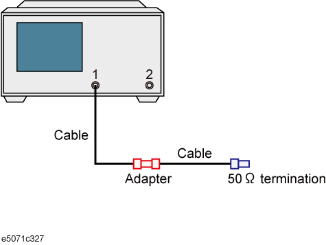
This section introduces an example of how to detect the location of a mismatch that occurs in a cable by using the time domain function.
In this example, a DUT is evaluated according to the steps.
|
Step |
Description |
|
Set the measurement conditions. |
|
|
Execute calibration. |
|
|
Connect the DUT. |
|
|
4. Auto Scale |
Execute auto scale. |
|
Set the time domain function. |
Follow these steps to set the measurement conditions:
|
Setting Description |
Key Operation |
|
Presetting |
Preset > OK |
|
Stop frequency: 3 GHz |
Stop > 3 > G/n |
|
Number of points: 201 |
Sweep Setup > Points > 2 > 0 > 1 > x1 |
|
Specifying the low-pass mode sweep condition |
Analysis > Transform > Set Freq Low Pass |
|
Measurement parameter: S11 |
Meas > S11 |
By following 1-Port Calibration (reflection test), execute 1-port calibration on port 1.
Connect the DUT as shown below.

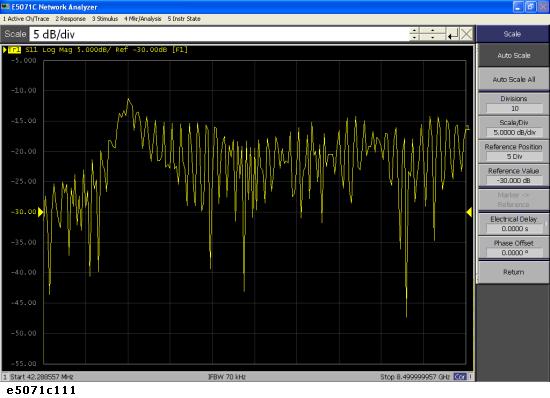
Execute the auto scale function.
|
Setting Description |
Key Operation |
|
Executing auto scale |
Scale > Auto Scale |

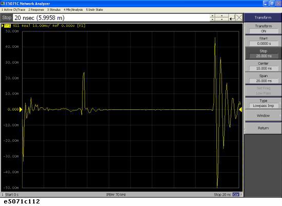
Set the conversion function to display the response in the time domain. If you enable this setting, the response in time domain is displayed as shown figure below. A peak indicating a small mismatch appears at the location of the connector.
|
Setting Description |
Key Operation |
|
Data format: real |
Format > Real |
|
Setting the transformation type to low-pass impulse |
Analysis > Transform > Type > Lowpass Imp |
|
Setting the window type to maximum. |
Window > Maximum |
|
Setting the display range: from 0 s to 20 ns |
Start > 0 > x1 |
|
Stop > 2 > 0 > G/n |
|
|
Enabling the transformation function |
Transform (set to ON) |
|
Executing auto scale |
Scale > Auto Scale |
