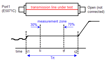
Measuring the characteristic impedance of single-ended transmission line within a defined zone.

Ensure E5071C-TDR application is in Advanced Mode in order to follow this example.
Before beginning to make measurement on PCB impedance, we need:
Other topics about Measurement Examples
Click Setup > Setup Wizard.
Select Deskew and click Next.
Select Single Ended 1-Port and click Next.
Follow the instruction and click Deskew. When finish, click Next.
Follow the instructions and click Measure. When finish, click Next.
Click Apply and Finish.
Using E5071C-TDR application GUI,
Disconnect the DUT.
Click Trace > 1 and double-click on the trace.
Click TDR/TDT > Parameters > Linear (under Format).
Click AutoScale > X & Y to adjust timebase for the entire response of the DUT is visible.
Click Marker > 1.
Using Softkey (on the right side of the screen),
Click Marker Search > Target > Target Value.
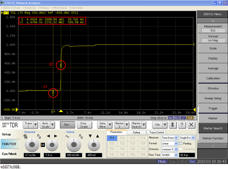
Type 0.5 target value into the entry box. This steps locate the instant t1 on the TDR waveform where the open discontinuity occurs.
Connect the DUT.
Using E5071C-TDR application GUI,
Click Marker > 2.
Using Softkey (on the right side of the screen),
Click Marker Search > Target > Target Value.
Type 0.5 target value into the entry box. This steps locate the instant t2 on the TDR waveform where the open discontinuity occurs.
Calculate the measurement zone using the formulas below.
Compute the round trip propagation time of the transmission line:
Trt = t2 -t1 = 1.68 ns - 0 = 1.68 ns (refer to the figure below)
Determine the initial instant, ti, of the measurement zone:
ti = t1 + 30%Trt = 0 + (0.3)×1.68 ns = 0.50 ns
Determine the final instant, tf, of the measurement zone:
tf = t1 + 70%Trt = 0 + (0.7)×1.68 ns = 1.18 ns

Click TDR/TDT > Parameters > Impedance (Under Format).
Click TDR/TDT. Type in 25 into scale/div (left) entry box under Vertical.
Click TDR/TDT. Type in -75 into position (right) entry box under Vertical.
Using Softkey,
Click Marker Search > Search Range > Start. Type in 0.5 ns in the entry box.
Click Marker Search > Search Range > Stop. Type in 1.18 ns in the entry box.
Click Marker Search > Search Range > Search Range to enable search range.
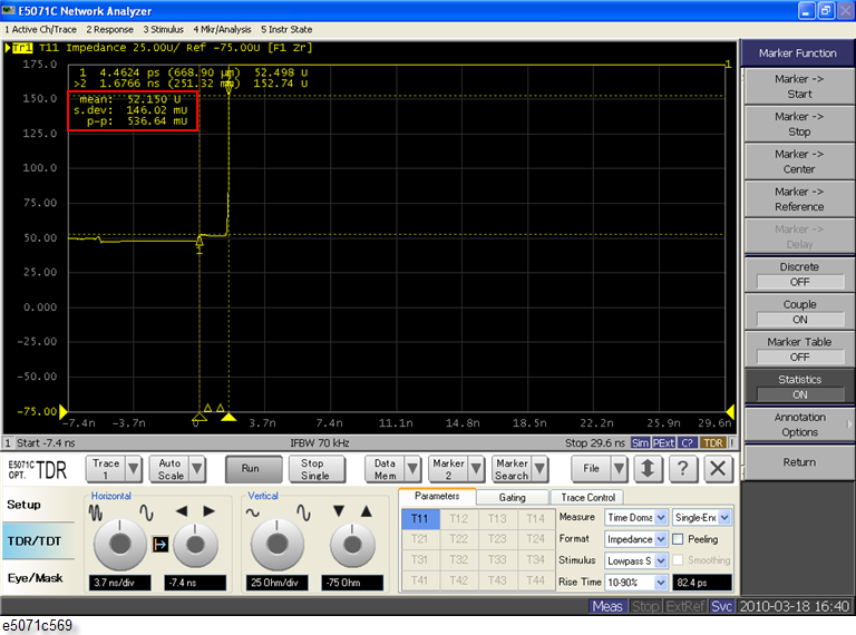
Click Marker Function > Statistics to enable statistics and measure the characteristic impedance.

The characteristic impedance is the mean value, 52.15 U.