Other topics about Time Domain Analysis
This section describes masking and the identification of the mismatch type, which are important for analyzing the response in the time domain.
Masking is a phenomenon in which a mismatch at a location near the calibration surface affects the response at the next mismatch location. This occurs because energy reflected by a mismatch at the location nearest to the calibration surface does not reach the next mismatch location. For example, when you measure the reflection of a cable that has 2 mismatch locations reflecting 50% of the input voltage, the first mismatch reflects 50% of the measurement signal. The remaining 50% reaches the next mismatch and its 50%, which is 25% of the entire measurement signal, is reflected. Therefore, in the response in the time domain, the second mismatch looks smaller.
In this example, the transmission line is assumed to have no loss. However, because there actually is loss, the signal is attenuated as the distance from the calibration surface becomes greater.
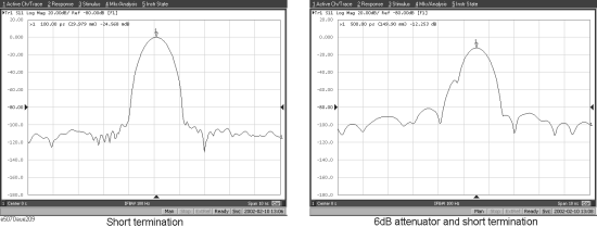
The following figure shows an example of masking due to loss. It compares masking when a short termination is directly connected to the calibration surface and masking when a 6-dB attenuator is inserted. In either case, total reflection occurs at the short termination. In the latter case, the signal is attenuated in both ways, and the return loss appears to be - 12 dB.
Example of masking

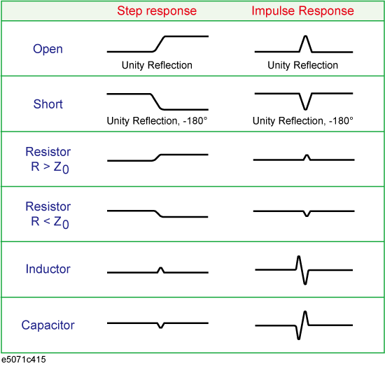
The transformation in the low pass mode simulates the response in the TDR measurement. In addition to mismatch locations, the response includes information on the mismatch type.
The following shows each mismatch type and the response waveform corresponding to it. In the low pass mode, you can simulate the response of the step signal and the impulse signal. From the viewpoint of mathematics, the response of the impulse signal is the waveform obtained by differentiating the response of the step signal.
