The performance of the network analyzer is specified in two ways: system specifications, and instrument specifications. It is the end users' responsibility to determine which set of specifications is applicable to their use of the E5071C.
A network analyzer measurement “system” includes the analyzer, calibration kit, test cables, and any necessary adapters. The system verification software in the E5071C is used to verify the system’s conformance to the “system” specifications. A “pass” result demonstrates that the analyzer, test cables, and adapters, perform correctly as a system. It DOES NOT demonstrate that any one component performs according to its individual specifications. A change to any part of this measurement system requires a re-verification of the system.
Instrument specifications specify the network analyzer’s uncorrected measurement port characteristics and its output and input behavior. The E5071C performance tests are used to verify the analyzer’s conformance to “instrument” specifications.
The System Verification utility verifies the E5071C's system specifications by automatically measuring the magnitude and phase for all four S-parameters for each verification device, and comparing the values against the following:
Factory measured data from files on the verification disk
Limit lines based on the measurement uncertainty
System Verification requires the use of a Calibration Kit and Verification Kit which has been certified within the past 12 months by Keysight. System Verification can NOT be used to perform this kit certification.
Other topics about Maintenance
Although the performance for all S-parameters is measured, the S-parameter phase uncertainties for reflection measurements are less important for verifying system performance. Therefore, the limit lines will not appear on the printouts.
85055A, Type-N, 300 kHz - 18.0 GHz
85051B, 7 mm, 300 kHz - 18 GHz
The combination of Calibration Kit and Verification Kit that can be used is as follows:
|
Cal kit |
Connector |
Kit Type |
Verification Kit |
Minimum Frequency |
Maximum Frequency |
|
85033D |
3.5 mm |
Mechanical |
85053B |
- |
6 GHz |
|
85033E |
3.5 mm |
Mechanical |
85053B |
- |
9 GHz |
|
85052D |
3.5 mm |
Mechanical |
85053B |
- |
26.5 GHz |
|
85052C |
3.5 mm |
Mechanical |
85053B |
- |
26.5 GHz |
|
85093B |
3.5 mm |
ECal** |
85053B |
300 kHz |
9 GHz |
|
85093C |
3.5 mm |
ECal** |
85053B |
300 kHz |
9 GHz |
|
N4433A |
3.5 mm |
ECal** |
85053B |
300 kHz |
20 GHz |
|
N4691A |
3.5 mm |
ECal** |
85053B |
10 MHz |
26.5 GHz |
|
N4691B |
3.5 mm |
ECal** |
85053B |
300 kHz |
26.6 GHz |
|
85032B/E |
Type-N |
Mechanical |
85055A |
- |
6 GHz |
|
85032F |
Type-N |
Mechanical |
85055A |
- |
9 GHz |
|
85054D |
Type-N |
Mechanical |
85055A |
- |
18 GHz |
|
85092B |
Type-N |
ECal** |
85055A |
300 kHz |
9 GHz |
|
85092C |
Type-N |
ECal** |
85055A |
300 kHz |
9 GHz |
|
N4432A |
Type-N |
ECal** |
85055A |
300 kHz |
18 GHz |
|
N4690A |
Type-N |
ECal** |
85055A |
10 MHz |
18 GHz |
|
N4690B |
Type-N |
ECal** |
85055A |
300 kHz |
18 GHz |
|
85031B |
APC-7mm |
Mechanical |
85051B |
- |
6 GHz |
|
85050C |
APC-7mm |
Mechanical |
85051B |
- |
18 GHz |
|
85050D |
APC-7mm |
Mechanical |
85051B |
- |
18 GHz |
|
85091B |
APC-7mm |
ECal** |
85051B |
300 kHz |
9 GHz |
|
85091C |
APC-7mm |
ECal** |
85051B |
300 kHz |
9 GHz |
|
N4696A |
APC-7mm |
ECal** |
85051B |
10 MHz |
18 GHz |
|
N4696B |
APC-7mm |
ECal** |
85051B |
300 kHz |
18 GHz |
|
N4431A* |
3.5 mm |
ECal** |
85053B |
300 kHz |
9 GHz |
|
N4431B* |
3.5 mm |
ECal** |
85053B |
9 kHz |
13.5 GHz |
|
N4431A* |
Type-N |
ECal** |
85055A |
300 kHz |
9 GHz |
|
N4431B* |
Type-N |
ECal** |
85055A |
9 kHz |
13.5 GHz |
The results from the verification kit other than following combination are not warranted specification: _________________________________________________________________________________________________
E5071C 3GHz, 4.5GHz, 6.5GHz, 8.5GHz (Option 230/235/240/245/260/265/280/285/430/435/440/445/460/465/480/485)
Calibration Kit: 85032F, 85033E Electronic calibration (ECal) module: 85092C, 85093C ______________________________________________________________________________________________________________
E5071C 14GHz, 20GHz (Option 2D5/2K5/4D5/4K5)
Calibration Kit: 85052D
* The connection of the N4431x is for the thru path A-B, C-D, A-D, and B-C.
** The supported connector type is "male-female".
The test port cables specified for the E5071C have been characterized for connector repeatability, magnitude and phase stability with flexing, return loss, insertion loss, and aging rate. Since test port cable performance is a significant contributor to the system performance, cables of lower performance will increase the uncertainty of your measurement. It is highly recommended that the test port cables be regularly tested.
If the system verification is performed with a non-Keysight cable, ensure that the cable meets or exceeds the operation of the specified cable.
Flex Factor determines how much of the cable phase uncertainty to include in determining the limit lines.
Set to 0% (zero) if the cables are held down in a fixture and are not allowed to move during the calibration and verification.
Set to 100% if the cables are allowed to move a lot.
Non-Keysight calibration kits are not recommended nor supported.
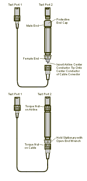
When you are using the airlines in the Verification Kit, observe the following practices to ensure good measurement techniques.
Be very careful not to drop the airline's center or outer conductor. Damage will result if these devices are dropped.
Use proper Electro-Static Discharge (ESD) procedures.
Clean your hands or wear gloves as skin oils will cause a change in electrical performance.

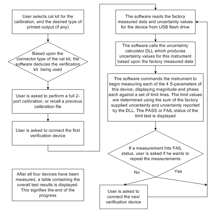
The operational flow of the software is depicted by the flowchart shown below.
There are four tabs in the E5071C System Verification program:
Run
Configure
Overview
Help
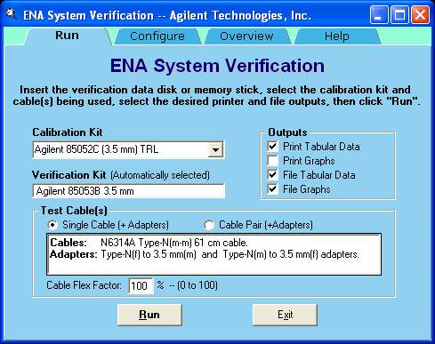
Calibration Kit: Select the calibration kit or ECal module that is being used.
Verification Kit: The corresponding Verification Kit to use appears in the Verification Kit box. Refer to the combination of Calibration Kit and Verification Kit table.
Test Cable(s): Select the method of connecting ports and Calibration/Verification Kit of E5071C. It is necessary to connect Calibration Kit and Verification Kit to E5071C with the same cable connection.
When calibration or verification is measured (2 port measurement), E5071C ports are connected to ports of kit by the following options:
Single Cable: One side of the port is connected to the port of E5071C and kit directly. The other port is connected through Cable.
Cable Pair: Both ports are connected to both ports of E5071C and kit through Cable.
Cable Flex Factor: Flex Factor determines how much of the cable phase uncertainty should be included in determining the limit lines.
Set to 0% (zero) if the cables are held down in a fixture and are not allowed to move during the calibration and verification.
Set to 100% if the cables are allowed to move extensively.
Outputs: Select the Verification result output format from one of the following options.
Print Tabular Data: Prints the Verification data in tabular form which includes measured data and uncertainty limits.
Print Graphs: Prints the Verification data in graphical form. It is the screen image of the Verification result of a measurement is printed as output. The graphic form includes the measured data trace, factory supplied data trace and uncertainty limits.
File Tabular Data: Writes the Verification data in tabular form to a text file. The file is stored as SysVer(Date)(Time)(Ports).txt and saved under the directory of “D:\SysVer”, where Date=yyyymmdd (ex. 20101016), Time=hhmm (ex. 1520), Ports=Pnm (ex. P12). An example of a filename is SysVer201010161520P12.txt.
File Graphs: Saves a screen image in .PNG format. The file is stored as SysVer(Date)(Time)(Ports)(DevNo)(Param).png and saved under the directory of “D:\SysVer”, where DevNo=Device Number (ex. Dev1), Param=M or P (M is for LogMag or LinMag, P is for Phase). An example of a filename is SysVer201010161520P12Dev1M.png.
Click Run button to start the Verification procedure. Follow the instructions on the E5071C for performing the System Verification, inserting the Verification devices as prompted.
Click Exit button to exit the Verification program.
For the System Verification to be truly adequate, the software must measure all devices in the kit with a recent calibration applied. Removing and reattaching any test port cables or adapters invalidates all previous calibrations.
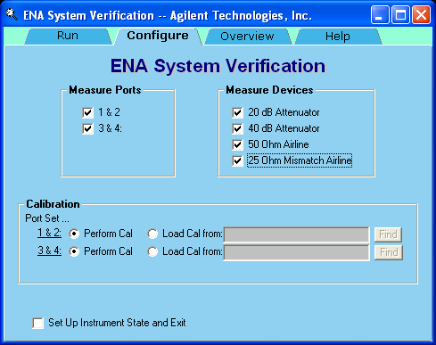
Measure Ports: The port pair that executes verification measurement is selected.
1 & 2 : Port 1 and Port 2
3 & 4 : Port 3 and Port 4 (This option is not displayed on 2 port E5071C model)
In 4 ports E5071C model, both options are selected as default. At least one option should be selected.
In 2 ports E5071C model, option 1 & 2 is selected and it cannot be changed.
Measure Devices: Select the device in the verification kit to execute the measurement from the following options. By default, all options are selected and at least one option must be selected. In general, all items should be measured. When you disable all items, 20 dB Attenuator is automatically selected:
20 dB Attenuator
40 dB Attenuator
50 Ohm Airline
25 Ohm Mismatch Airline
Calibration: Select the method of acquiring the calibration data in the Verification procedure from the following options.
Perform Cal: Calibration data is acquired from the actual Calibration measurement.
Load Cal from: Calibration data is recalled from the State file. The State file should include the full 2 port calibration for the corresponding ports.
The radio button for unselected options are disabled.
In 2 ports E5071C model, the option and entry for Port 3 & 4 is not displayed.
Set Up Instrument State and Exit: If this check box is checked, only set up is performed and the program is terminated thereafter without executing the verification process. If this check box is un-checked, the verification process is executed once the set up is performed.
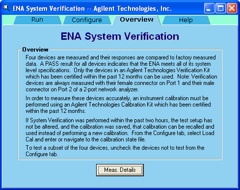
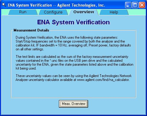
This tab displays the overview of the ENA System Verification. Click Meas. Details to view the Verification measurement details. Click Meas. Overview to toggle back to ENA System Verification overview.
This tab displays the information of the ENA System Verification and links to online help topics.
If you want printed test outputs, connect a printer to the E5071C.
Let the E5071C warm up for at least 90 minutes.
Insert the Verification Kit USB flash drive into the E5071C's USB port.
On the System menu, point to Service Menu > Test Menu > System Verification. The System Verification window is displayed.
Select calibration kit or ECal module in the Calibration Kit box.
Setup the configuration in Run tab and Configure tab as required.
If you click Cancel, Abort, Abort All Measurements button in one of the following steps, the program returns to the main menu.
Click the Run button.
Type the serial number for both Calibration kit and Verification kit, then click the Continue button.
The user-entered serial number is printed on the Verification result report. If not necessary, blank is acceptable.

At single cable connection for the E5071C option x3x/x4x/x6x and x8x, a precision m-m adapter at port 1 and m-f cable at port 2 can be used instead for easy airline connection. The test result is regarded as typical.

Calibration Execution:
Press Cal key on the E5071C front panel and execute full 2 ports calibration.
Once you have completed calibration, click OK in the following dialog box to proceed with the next step.

When the calibration is performed correctly, the following dialog box is displayed. If you want to save the calibration result into the State file, click Yes. Otherwise, click No.

If the Load Cal from is selected from the Calibration option of the Configure tab, then this step is skipped. Instead of executing calibration, the selected State file is recalled. Then, the calibration data is set up.
Verification Execution:
Execute the Verification measurements for the devices selected under Measure Devices options of the Configure tab.
Follow the instruction displayed in the dialog.
Connect the Verification Kit device, then click Measure This Device to measure. The result is displayed in the graph display area on the E5071C screen.

Once the measurement is completed, the following dialog is displayed:

Click Display Phase to change the display format of the graph into Phase. Instruction on the next step for the next device measurement (40 dB Attenuator) is displayed in the following dialog box:

Click Remeasure This Device to return to the previous dialog so that you can re-measure the same device (20 dB Attenuator).
Similarly, repeat step c to e in order to measure all the devices.
Click Remeasure Previous Device to return to the previous measurement (in this example, 20 dB Attenuator).
Displaying the result of Verification Measurement
Once all the verification measurements for the selected devices are completed, the following result is displayed. It shows the PASS and FAIL status for each measurement.

Click Close to close the dialog box.
Saving the Verification result into a file
If the File Tabular Data is selected as the Outputs option in the Run tab, the following dialog is displayed. If it is not selected, this step is skipped.

Click OK to save the result into the file as shown in the dialog box.
If both pairs (1&2 and 3&4) are selected under Measure Ports option of Configure tab for 4 port E5071C, follow the procedure from the step 10 onwards for one pair, then repeat them for another pair.
If only one pair is selected, follow the procedure from step 5 onwards.
Repeat this verification test. Make good connections with correct torque specifications for each verification device.
Disconnect, clean and reconnect the device that failed the verification test. Then measure the device again.
If the analyzer still fails the test, check the measurement calibration.
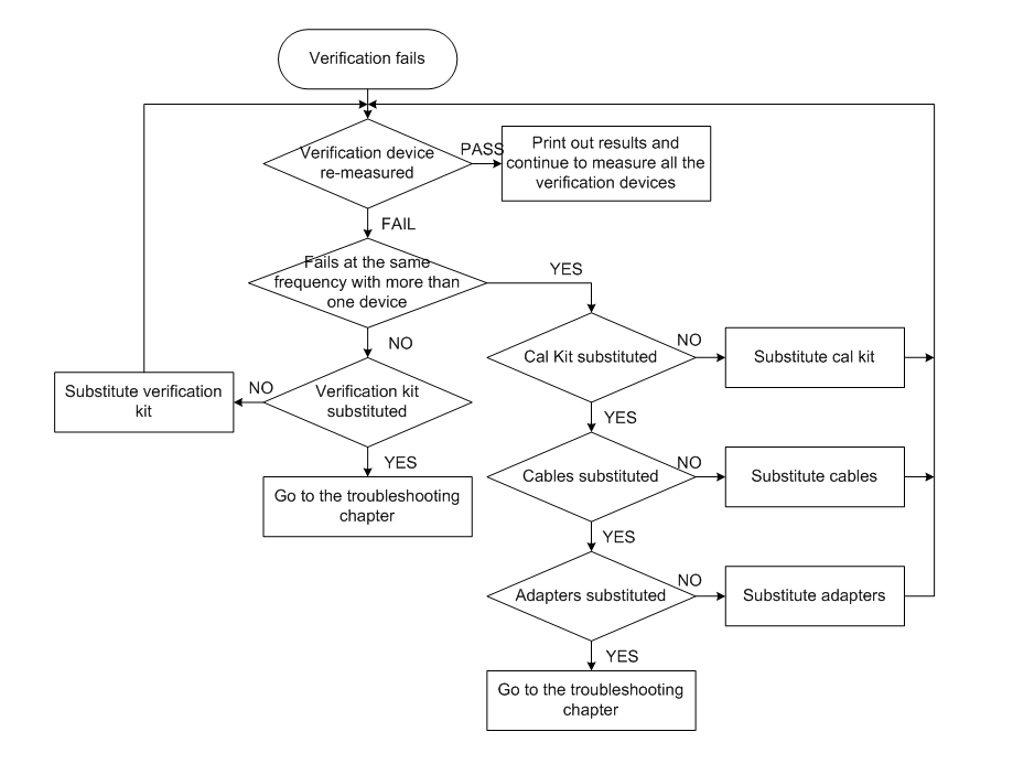
Refer to the graphic below, for additional troubleshooting steps.
The type of output for the Verification result can be selected under Outputs in the Run tab. Use these printouts to determine whether your measured data falls within the total uncertainty limits at all frequencies.
The result includes the following items:
Header information
E5071C: model number, serial number, verification test time and day
Calibration Kit: model number, (serial number)
Verification Kit: model number, (serial number)
Measured device, Parameter
Data for each test point
Frequency
Lower limit (defined by the total system uncertainty specification)
Measurement result
Upper limit (defined by the total system uncertainty specification)
Test status (PASS or FAIL). Asterisks (**) is displayed at fail points.
Upper limit line (defined by the total system uncertainty specification)
Lower limit line (defined by the total system uncertainty specification)
Measured value at factory (Memory trace)
Measured value (Data trace)
Parameter name (S11, S12 etc.), format (Lin, Log or Phase)
Device name and serial number