Other topics about Communication with External Devices
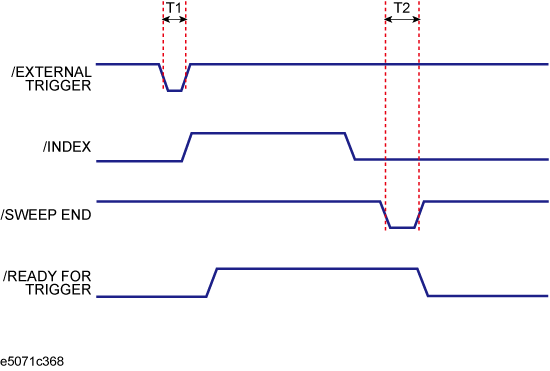
This section shows the typical timing chart of I/O port Signal.

|
|
Minimum value |
Typical Value |
Maximum value |
|
|
T1 |
Pulse width of /EXTERNAL TRIGGER |
- |
- |
|
|
T2 |
Pulse width of /SWEEP END |
10 µs |
12 µs |
- |
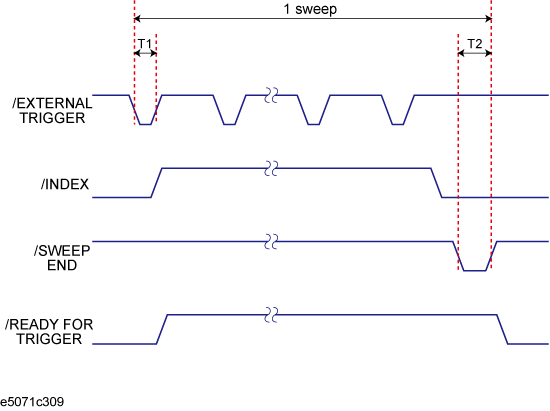
When both the point trigger function and the low-latency external trigger mode are on, the /EXTERNAL TRIGGER signal must be inputted for each measurement point during a single sweep. The /INDEX signal goes to the High level before staring measurement of the first measurement point and returns to the Low level after the completing measurement of all measurement points.
The /READY FOR TRIGGER signal goes to the Low level when the instrument is ready to accept the trigger signal for the first point and then goes to the High level when the trigger signal for the first point is received.
When measurement of all measurement points is completed and the instrument is ready to receive the trigger signal for the first point of the next sweep, this signal goes to the Low level again.
When the point trigger function is on and the low-latency external trigger mode is off, the /READY FOR TRIGGER signal goes High each time a trigger signal is received and goes Low when measurement of each measurement point is completed and the instrument is ready to accept a trigger for the next measurement point.
The times of T1 and T2 are the same as those when the point trigger function is off. For more information, see Timing chart of I/O Port Signal(Point trigger function:off).
|
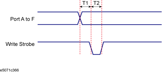
T1 |
Response time of write strobe signal |
1 µs |
|
T2 |
Pulse width of write strobe signal |
1 µs |
|
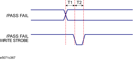
T1 |
Response time of /PASS FAIL write strobe |
1 µs |
|
T2 |
Pulse width of /PASS FAIL write strobe |
1 µs |
When the average trigger function is activated, the fail and write strobe signals are output at the time that the average test result shows "failed" on a certain channel.
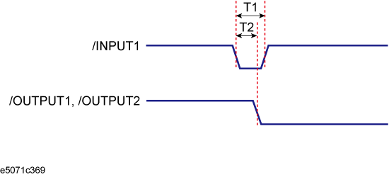
|
|
Minimum value |
Maximum value |
|
|
T1 |
Pulse width of /INPUT1 |
1 µs |
- |
|
T2 |
Response time of /OUTPUT1, /OUTPUT2 |
0.4 µs |
0.6 µs |