This section illustrates how to use the segment sweep function to evaluate a SAW bandpass filter with a center frequency of 947.5 MHz.
Here, the DUT is evaluated by following the steps.
|
Step |
Description |
|
The segment sweep conditions are determined according to the characteristics of the DUT. |
|
|
The segment sweep conditions are entered in the E5072A. |
|
|
The segment sweep is selected as the sweep type. |
|
|
A 2-port ECal is performed between the test ports connecting the DUT. |
|
|
The DUT is connected. |
|
|
A trigger is applied to perform the measurement. |
|
|
The choice is made between frequency base and order base as the method of displaying segments. |
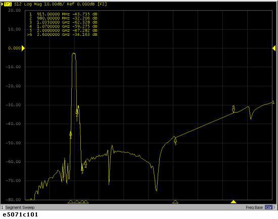
The following figure shows the results of evaluating the transmission characteristics of the SAW bandpass filter in the range of 440 MHz to 3 GHz by using the linear sweep.
Transmission characteristics of SAW bandpass filter (440 MHz to 3 GHz, linear sweep)
The measurement conditions are determined for each frequency range. Here, the segment sweep is performed following the sweep conditions shown in the following table.
|
Frequency Range |
Measurement Conditions |
||
|
Start |
Stop |
Number of Points |
IF Bandwidth |
|
440 MHz |
915 MHz |
47
|
70 kHz
|
|
915 MHz |
980 MHz |
130 |
100 kHz
|
|
980 MHz |
1.035 GHz |
55
|
70 kHz
|
|
1.07 GHz |
2 GHz |
93
|
70 kHz
|
|
2.6 GHz |
3 GHz |
41 |
70 kHz
|
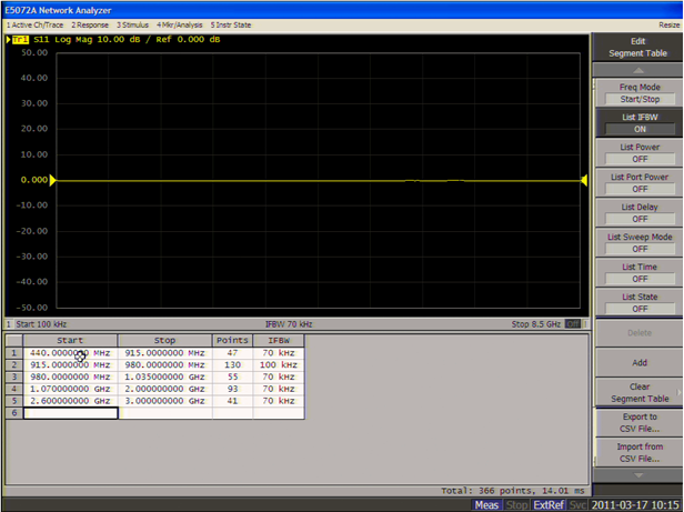
Follow the steps below to make entries in the segment sweep table.
Display the segment table.
|
Setup Description |
Key Operation |
|
Presetting |
Preset > OK |
|
Displaying the segment table |
Sweep Setup > Edit Segment Table |
Display the IF bandwidth setting column in the segment table.
|
Setup Description |
Key Operation |
|
Moving the focus to the softkey menu |
Focus |
|
Display of IF bandwidth setting column: ON |
List IFBW > ON |
When setup items (power level, delay time, sweep mode, and sweep time in this case) are not displayed in the segment table, the setting for the channel in use applies to all segments.
Enter the setup data in the segment table.
|
Setup Description |
Key Operation |
|
Moving the focus to the segment table (select) |
Focus |
|
Segment 1 |
|
|
Start frequency: 440 MHz |
4 > 4 > 0 > M/µ |
|
Stop frequency: 915 MHz |
9 > 1 > 5 > M/µ |
|
Number of points: 47 |
4 > 7 > x1 |
|
IF bandwidth: 70 kHz |
7 > 0 > k/m |
|
Segment 2 |
|
|
Start frequency: 915 MHz |
9 > 1 > 5 > M/µ |
|
Stop frequency: 980 MHz |
9 > 8 > 0 > M/µ |
|
Number of points: 130 |
1 > 3 > 0 > x1 |
|
IF bandwidth: 100 kHz |
1 > 0 > 0 > k/m |
|
Segment 3 |
|
|
Start frequency: 980 MHz |
9 > 8 > 0 > M/µ |
|
Stop frequency: 1.035 GHz |
1 > . > 0 > 3 > 5 > G/n |
|
Number of points: 55 |
5 > 5 > x1 |
|
IF bandwidth: 70 kHz |
7 > 0 > k/m |
|
Segment 4 |
|
|
Start frequency: 1.07 GHz |
1 > . > 0 > 7 > G/n |
|
Stop frequency: 2 GHz |
2 > G/n |
|
Number of points: 93 |
9 > 3 > x1 |
|
IF bandwidth: 70 kHz |
7 > 0 > k/m |
|
Segment 5 |
|
|
Start frequency: 2.6 GHz |
2 > . > 6 > G/n |
|
Stop frequency: 3 GHz |
3 > G/n |
|
Number of points: 41 |
4 > 1 > x1 |
|
IF bandwidth: 70 kHz |
7 > 0 > k/m |
Completed segment table
The segment sweep is selected as the sweep type.
|
Setup Description |
Key Operation |
|
Sweep type: Segment sweep |
Sweep Setup > Sweep Type > Segment |
In this step, a 2-port Cal using the ECal is executed on both ports.
1. Connect the ECal module across test ports 1 and 2.
Connecting the ECal module
2. Execute the 2-port ECal.
|
Setup Description |
Key Operation |
|
Execute a 2-port Cal between test ports 1 and 2 |
Cal > ECal > 2 Port Cal |
The DUT is connected across test ports 1 and 2.
Connecting the DUT
A trigger is applied to perform the measurement.
|
Setup Description |
Key Operation |
|
Trigger mode: Single |
Trigger > Single (Or Continuous) |
|
Scale: Autoscale |
Scale > Auto Scale (Or Auto Scale All) |
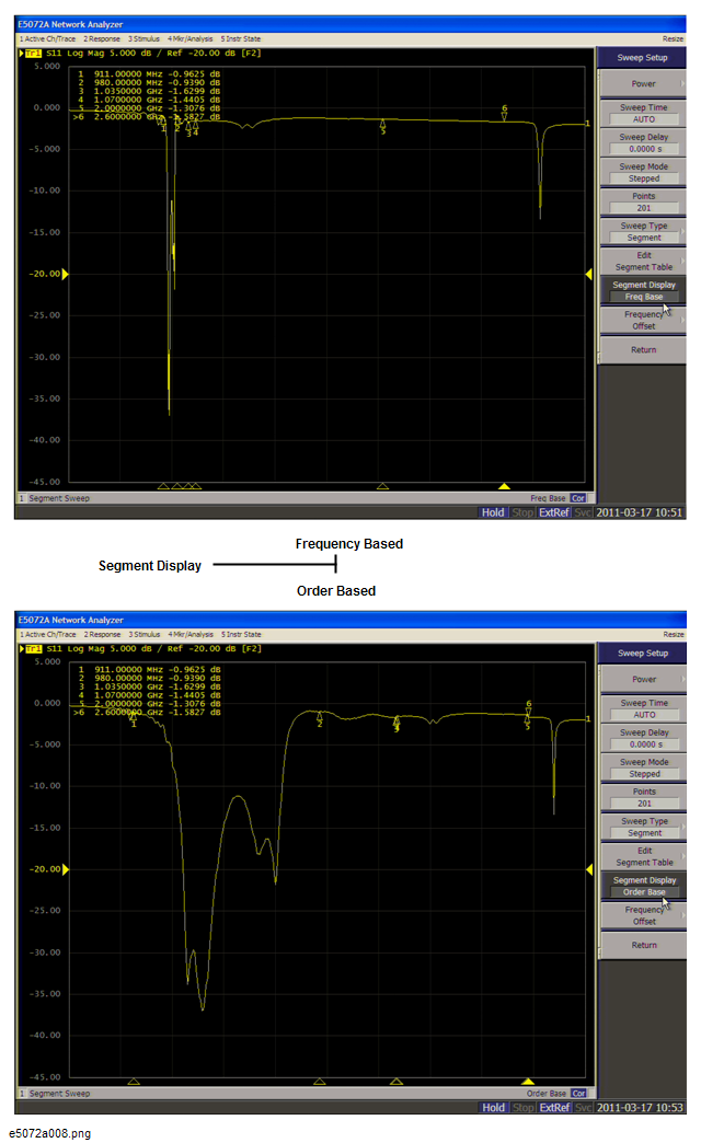
The choice is made between frequency base and order base as the segment display mode.
|
Setup Description |
Key Operation |
|
Segment display: Frequency base or order base |
Sweep Setup > Segment Display > Frequency Base | Order Base |
Segment display: Frequency/Order base