Other topics about Setting Measurement Conditions
The E5072A allows you to use up to 160 channels (when the number of traces is up to 9) to perform measurement under 160 different stimulus conditions.
For each channel, up to 4, 6, 9, 12 or 16 traces (measurement parameters) can be displayed. Because multiple traces can be displayed for each channel, no feature is provided to link the stimulus conditions between channels, and each channel is always independent of the others. In other words, for the E5072A, you need to set the measurement conditions and execute calibration for each channel you use for measurement.
With the E5072A, you can change the number of available channels and the upper limit of the number of traces. If you change the upper limit setting, you need to restart the firmware of the E5072A. Therefore, first, set the upper limit appropriately depending on the numbers of channels and traces necessary for your measurement.
When you set items where the target is channels/traces (refer to Parameter setting for each setup item), the actual target is the selected (active) channel/trace. You can specify only the displayed channels/traces as active channels/traces. Therefore, set the display of channels/traces before setting the measurement conditions.
You can select the upper limits of the number of channels and the number of traces from the following combinations:
|
Channels |
Traces |
Maximum |
Supported Revision |
Note |
|
1 |
4 |
1601 |
All |
You may want to select the "1-channel, 4-trace" or "2-channel, 4-trace" configuration to save the time required to save/recall the instrument state file, since this takes longer with other configurations. More channels and traces requires longer measurement time. |
|
2 |
4 |
1601 |
For these setup, press After the configuration setup is applied, memory swap may occur during the measurement. The instrument may seem to pause during the measurement. |
|
|
4 |
16 |
1601 |
||
|
9 |
9 |
1601 |
||
|
12 |
6 |
1601 |
||
|
16 |
4 |
1601 |
||
|
16 |
16 |
1601 |
||
|
24 |
12 |
1601 |
||
|
36 |
9 |
1601 |
||
|
2 |
8 |
1601 |
||
|
2 |
8 |
10001 |
||
|
2 |
16 |
10001 |
||
|
1 |
4 |
20001 |
||
|
72 |
9 |
401 |
||
|
96 |
9 |
201 |
||
|
160 |
9 |
201 |
Its important to realize that the combination used to save a state file must be the same used to recall it; that is, you cannot save a state file with one combination of channels/traces and recall it with another combination. For more details, see Saving and Recalling Instrument State.
The selection procedure is as follows:
Press System > Misc Setup > Channel/Trace Setup. (System > Service Menu > Channel/Trace Setup for some settings)
Press the desired softkey to select the upper limits of the number of channels and the number of traces.
The "New Channel/Trace configuration will take effect after firmware restart." dialog box appears.
Click OK.
Press any softkey or hardkey besides Preset.
The "Do you want to restart now?" dialog box appears.
Click Yes.
When selecting a multi-channel mode, it may take more time to restart the firmware. The screen may seem to freeze but will resume to normal operation once the settings are applied.
The measurement result for each channel is displayed on its dedicated window (channel window). You cannot have a single window to display the measurement results from more than one channel. This means that the setting of the window layout determines the number of channels displayed on the screen.
The execution of measurement for each channel does not depend on how the channel is displayed (channels that are not displayed can be measured). For information on performing measurement for each channel (trigger mode and trigger source), refer to Making Measurements.
The procedure for setting the window layout is as follows:
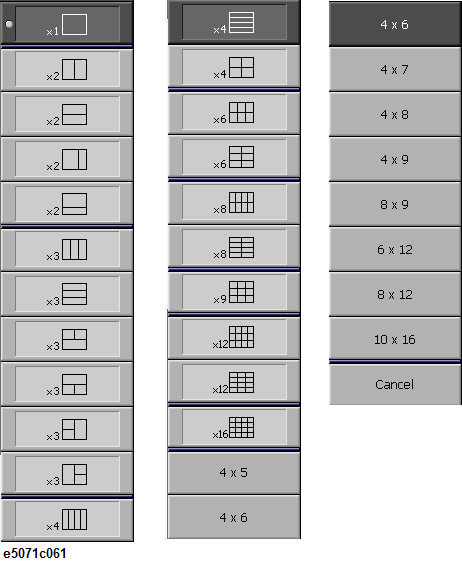
Press Display > Allocate Channels.
Press the desired softkey to select the window layout shown below.
Depending on the measurement parameters of the traces displayed for each channel, the necessary sweep is executed. For more information, refer to Sweep Order in Each Channel.
Specify the trace display by setting the number of traces (upper limit of displayed trace numbers). For example, if you set the number of traces to 3, traces 1 through 3 are displayed.
The procedure of setting the number of traces is as follows:
Press Channel Next or Channel Prev to select the channel for which you want to set the number of traces.
Press Display > Number of Traces.
Press the desired softkey to set the number of traces.
Traces are laid out and displayed in the order of the trace number according to the graph layout in the channel window.
You can select the graph layout from the windows layout.
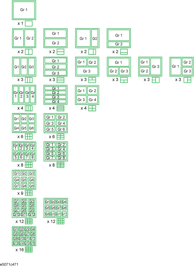
If the number of traces is less than the number of graphs, nothing is displayed in the remaining area. If the number of traces you set exceeds the number of graphs, excess traces are superimposed from the first graph. For example, if you select![]() as the graph layout and set the number of traces to 5, graph 1 (Gr1 in Graph layout) and graph 2 (Gr2 in Graph layout) display traces 1 and 4 and traces 2 and 5, respectively by superimposing, and graph 3 (Gr3 in Graph layout) displays only trace 3 as shown in the figure below.
as the graph layout and set the number of traces to 5, graph 1 (Gr1 in Graph layout) and graph 2 (Gr2 in Graph layout) display traces 1 and 4 and traces 2 and 5, respectively by superimposing, and graph 3 (Gr3 in Graph layout) displays only trace 3 as shown in the figure below.
The procedure for setting the graph layout is as follows:
Press Channel Next or Channel Prev to select the channel for which you want to set the graph layout.
Press Display > Allocate Traces.
Press the desired softkey to select the graph layout shown below.
The active channel refers to the channel whose settings can currently be changed. The window frame of the active channel is displayed brighter than the window frames of the other channels. To change the settings specific to a certain channel, you must first activate the channel.
To change the active channel, use the following hardkeys:
|
Hardkey |
Function |
|
Channel Next |
Change the active channel to the next channel with the larger channel number. |
|
Channel Prev |
Change the active channel to the previous channel with the smaller channel number. |
The active trace refers to the trace whose settings can currently be changed. The trace name on the screen (for example, Tr3) of the current active trace is highlighted and indicated with ![]() to the left. To change the settings specific to a certain trace, you must first activate the trace.
to the left. To change the settings specific to a certain trace, you must first activate the trace.
To select the active trace, use the following hardkeys:
|
Hardkey |
Function |
|
Trace Next |
Change the active trace to the next trace with the larger trace number. |
|
Trace Prev |
Change the active trace to the previous trace with the smaller trace number. |
The following table lists the parameters and indicates the setup item (analyzer, channel, or trace) that each parameter controls along with the applicable setup key(s).
|
Parameter |
Controlled Setup Items |
Setup Key(s) |
||
|
Analyzer |
Channel |
Trace |
||
|
Stimulus Settings |
|
|||
|
Sweep range |
|
x |
|
Start, Stop, Center, Span |
|
Power, CW frequency |
|
x |
|
Sweep Setup > Power |
|
Sweep time/Sweep delay time |
|
x |
|
Sweep Setup > Sweep Time, Sweep Delay |
|
Number of points |
|
x |
|
Sweep Setup > Points |
|
Segment sweep |
|
x |
|
Sweep Setup > Sweep Type, Edit Segment Table, Segment Display |
|
Sweep mode |
|
x |
|
Sweep Setup > Sweep Mode |
|
Trigger Settings |
|
|||
|
Trigger source |
x |
|
|
Trigger > Trigger Source/Restart/Trigger |
|
Trigger mode |
|
|
Trigger > Hold/Hold All Channels/Single/ Continuous/Continuous Disp Channels |
|
|
Response Settings |
|
|||
|
Measurement parameter |
|
|
x |
Meas |
|
Data format |
|
|
x |
Format |
|
Scale, Electrical delay, Phase offset |
|
|
Scale
|
|
|
Memory trace and data math |
|
|
x |
Display > Display/Data-> Mem/ Data Math |
|
Window title |
|
x |
|
Display > Edit Title Labe/ Title Label (ON/OFF) |
|
Graticule label in rectangular form |
|
x |
|
Display > Graticule Label (ON/OFF) |
|
Color inversion |
x |
|
|
Display > Invert Color |
|
Frequency display ON/OFF |
x |
|
|
Display > Frequency (ON/OFF) |
|
Display update ON/OFF |
x |
|
|
Display > Update (ON/OFF) |
|
Averaging |
|
x |
|
Avg > Averaging Restart/ Avg Factor/Averaging (ON/OFF) |
|
Smoothing |
|
|
x |
Avg > Smo Aperture/ Smoothing (ON/OFF) |
|
IF bandwidth |
|
x |
|
Avg > IF Bandwidth |
|
Calibration |
|
x |
|
Cal |
|
Marker |
|
|
Marker, Marker Search, Maker Fctn |
|
|
Analysis |
|
|||
|
Fixture simulator |
|
|
Analysis > Fixture Simulator |
|
|
Time domain |
|
|
x |
Analysis > Gating/ |
|
Parameter conversion |
|
|
x |
Analysis > Conversion |
|
Limit test |
|
|
x |
Analysis > Limit Test |
|
Saving and recalling data |
x |
|
|
Save/Recall |
|
Macro |
x |
|
|
Macro Setup, Macro Run, Macro Break |
|
System |
|
|||
|
Printing/Saving display Screen/Beeper/GRIB settings/Network Settings/Date & Time/Key Lock/Backlight/Firmware Revision/Service menu |
x |
|
|
System |
|
Preset |
x |
|
|
Preset |