Note: The E5080A does not support this function.
When creating equations using values from an external DC meter, it is important to understand how these values are stored in the VNA's data buffers and the conversion that occurs when used in an equation. For example, when a voltage is read from an external DC meter, the value is displayed on the VNA as you would expect. That is, if you are reading a voltage level of 2 V from the DC meter in a trace, the VNA will display a level of 2 V. However, the value stored in the VNA data buffers is not a voltage but is a unit-less value. Voltage, Amperes, dBm, and Watts values from an external DC meter are converted so that the format matches that of the data in the VNA internal receivers. In this way, all of the formats within the VNA are the same. This information is important when performing analysis using the Equation Editor because the trace data is the converted value.
Configure a DC Device
The following table shows the formats (which are selected from the Type setting on the External DC Meter Properties dialog) and corresponding equations that convert between external DC meter readings and the VNA representation when using the trace data in an equation.
Note: Z0 is the characteristic impedance (typically 50 Ohms), dcMeter is the value from the external DC meter, and pnaVal is the value stored in the VNA data buffers. All data types are REAL.
|
Formats |
DC Meter to VNA Data Conversion |
VNA to DC Meter Data Conversion |
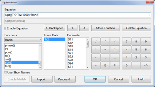
| V (volts - default) | +/-*sqrt((dcMeter*dcMeter/Z0)*1000) | +/-*sqrt((pnaVal*pnaVal/1000)*Z0) |
| A (amperes) | +/-*sqrt((dcMeter*dcMeter*Z0)*1000) | +/-*sqrt((pnaVal*pnaVal/Z0)/1000) |
| dBm | pow(10,dcMeter/20) | 20*log(pnaVal) |
| W (watts) | sqrt(dcMeter*1000) | pnaVal*pnaVal/1000 |
| K (kelvin) | N/A |
N/A |
| F (degrees) | N/A |
N/A |
| C (degrees) | N/A |
N/A |
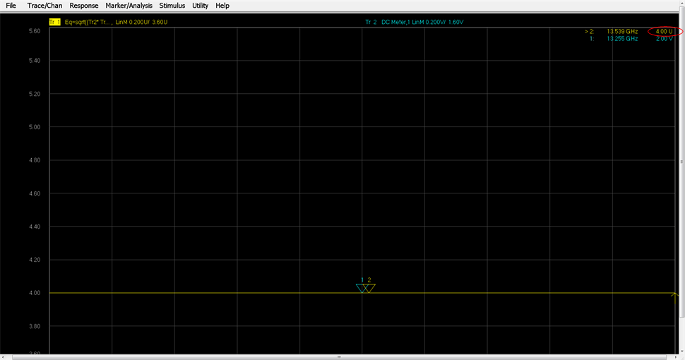
The following example shows how trace data is converted when used in an equation. In this example, a level of 2 V is read from an external DC meter.
Note: If the external DC meter is not displayed in the list, ensure that Active - Show in UI is checked in the External Device Configuration dialog.
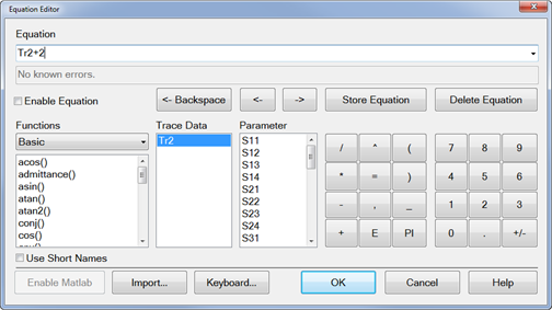
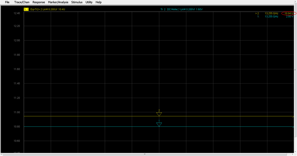
As shown in the table above, a voltage from an external DC meter is converted using sqrt((dcMeter*dcMeter/Z0)*1000). Therefore, substituting 2 for dcMeter in the equation and using 50 as Z0 results in a value of 8.94. Adding a value of 2 to the Trace 2 data, as defined in the Trace 1 equation, results in the displayed marker value of 10.94.