Prepare the following items
85052DH02
Open (female), Short (female), Load (female)
Calibration data file: This file is provided by USB memory furnished with the product.
16198A Option 010 (See the 16198A user's guide in https://www.keysight.com/manuals/16198a for details)
Fixture with a contact board and weight.
Adapter Box
Semi-rigid cable between Adapter Box and VNA
Short bar
Calibration Data (See the next step)
Torque wrenches
Each unit of 16198A Option 010 is calibrated at the factory and its calibration data is provided though Keysight support website.
Visit https://support.keysight.com/. Click Calibration Certificate in SERVICES.
Enter 16198A as the product number and your serial number. The serial number label is placed on the right side of fixture main unit. The serial number is 10 digit number beginning with MY or SG.(Do not use the number beginning with 1B)
Select SERVICE STATUS / CAL DOCS tab.
Confirm the certificate number starts with FACT-KEYS-1Bxxxxxxxxx. The 10 digit number beginning with 1B is the manufacturing ID. Confirm if this number is matched with the number labeled on the left side of fixture main unit.
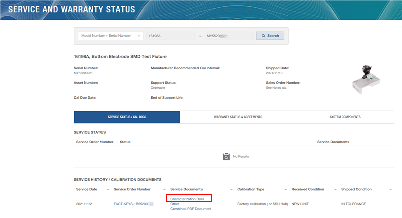
If the manufacturing ID number is NOT matched with the number labeled on the left side of fixure main unit, visit Support top page again and enter manufacturing ID number instead of the serial number.
Note: If your unit is repaired, the serial number is kept but the manufacturing number is changed if the calibration data is updated.Click the Characterization Data under Service Documents.
The calibration data is stored as ZIP file. Download and extract it. The file extension is ".dat".
Move the .dat file into E5080B.
Place the Adapter box in front of the E5080B and connect it with the E5080B through the Semi-Rigid cable. The tightening torque used is 0.9 Nm for 3.5 mm and 1.36 Nm for Type N