Other topics about Measurement Wizard Assistant
This section describes how to measure a multiport switch using the MWA software on the VNA. The measurement conditions for this measurement example are those suitable for a SP9T multiport switch. To measure another device under test (DUT), change the measurement conditions to suit the particular DUT.
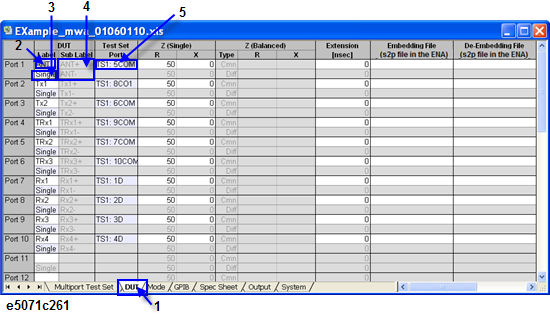
The DUT adopted in this example is a sample SP9T switch with the following configuration and should be connected to the E5092A with 10-port full crossbar configuration:
|
DUT Port Name |
Port Number |
Test Set |
|
ANT |
1 |
5COM |
|
Tx1 |
2 |
8COM |
|
Tx2 |
3 |
6COM |
|
TRx1 |
4 |
9COM |
|
TRx2 |
5 |
7COM |
|
TRx3 |
6 |
10COM |
|
Rx1 |
7 |
1D |
|
Rx2 |
8 |
2D |
|
Rx3 |
9 |
4D |
|
Rx4 |
10 |
3D |
The following test equipment is required for this example:
VNA (4-port VNA)
E5092A Configurable Multiport Test Set (option 020)
RF cables (for the connection between the DUT and the test set)
Control line cable
The sample DUT adopted in this example is a SP9T (Single-pole, 9-throw) 10-port switch. Transmission measurement for this switch should be performed for all the transmission paths between arbitrary ports, and reflection measurement for all ports of the DUT. The output port of the DUT is selected by 4-bit logic control DC voltage (2.8V as high and 0V as low).
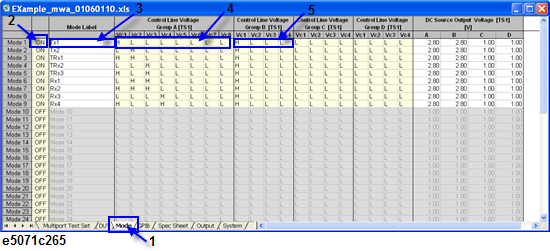
The truth table for the sample switch is as follows:
|
|
Group A |
Group B |
||||||
|
Connected Path |
Vc1 |
Vc2 |
Vc3 |
Vc4 |
Vc1 |
Vc2 |
Vc3 |
Vc4 |
|
Tx1 |
H |
L |
L |
L |
H |
L |
L |
L |
|
Tx2 |
L |
H |
L |
L |
H |
L |
L |
L |
|
TRx1 |
H |
H |
L |
L |
H |
L |
L |
L |
|
TRx2 |
L |
L |
H |
L |
H |
L |
L |
L |
|
TRx3 |
H |
L |
H |
L |
H |
L |
L |
L |
|
Rx1 |
L |
H |
H |
L |
H |
L |
L |
L |
|
Rx2 |
H |
H |
H |
L |
H |
L |
L |
L |
|
Rx3 |
L |
L |
L |
H |
H |
L |
L |
L |
|
Rx4 |
H |
L |
L |
H |
H |
L |
L |
L |
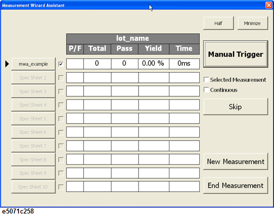
The measurement for the sample switch will be done using the front-end and the back-end applications of the MWA software. The measurement procedure is:
Generate a spec sheet (.mwa) with the MWA front-end application.
Copy the spec sheet on the VNA directory
Import the spec sheet with the MWA back-end application.
Perform necessary calibration measurement by calibration wizard in the back-end application.
Connect the DUT with the test set (RF cables, control lines)
Perform measurement with the back-end application.
The Front-end application consist of six sheets in which data for the sample switch will be entered as per the switch specifications. This sheet can be run on a normal PC:
1. Multiport Test Set sheet
Select a configuration of “E5092A X-10-Port” for 10-port full crossbar measurement.
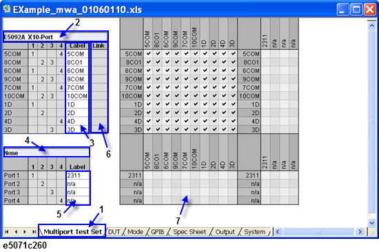
2. DUT sheet
Define the port name of the DUT and the connection with the multiport test set.
3. Mode sheet
Control logic voltage (Vc1 to Vc3) of the control line group A is applied to the DUT (logic A to C) and Vc4 is used for power supply of the DUT.
4. GPIB sheet
The SCPI commands can be sent to peripherals connected to the VNA via GPIB.
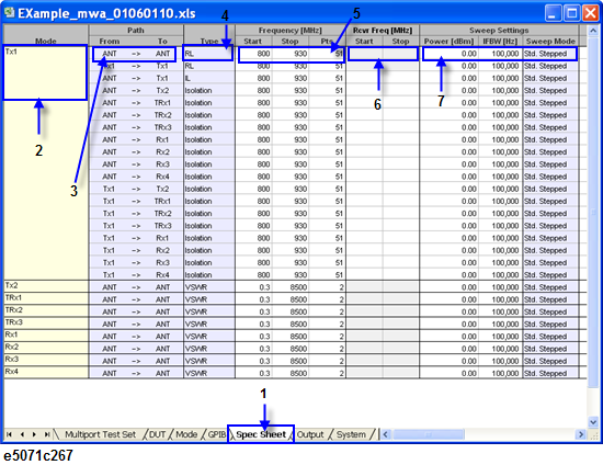
5. Spec Sheet sheet
Transmission measurement is performed between all paths for each operation mode of the DUT.
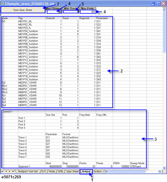
6. Output sheet
A spec sheet is generated by selecting the “Save Spec Sheet” button in the sheet. The traces are allocated automatically in measurement channels.
The Back-end application is installed on the VNA in which the data in mwa file will be imported as per follows:
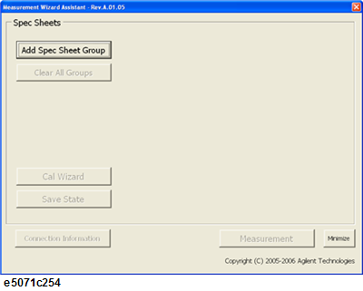
1. Importing a spec sheet
Select “Add Spec Sheet Group” in the main window, and select “Add Spec Sheets..” in the displayed window.
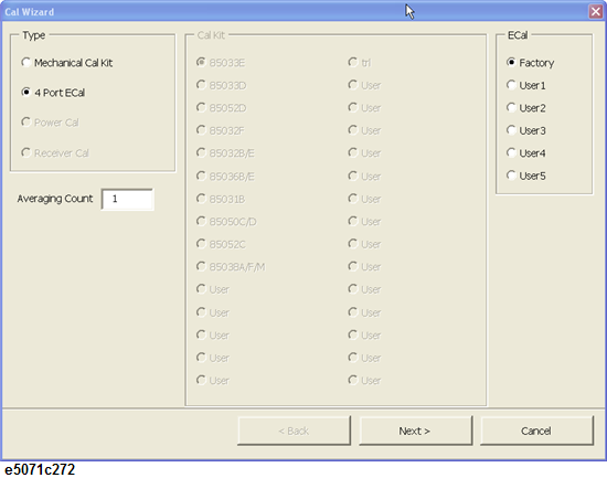
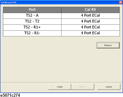
2. Performing calibration
Do a series of calibration measurement by following “step-by-step” calibration wizard.
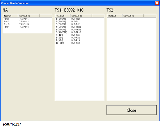
3. Connect the DUT and the test set
The connection between the DUT and the multiport test set is indicated in the connection check window.
4. Performing measurement