Last Updated: August 29, 2007
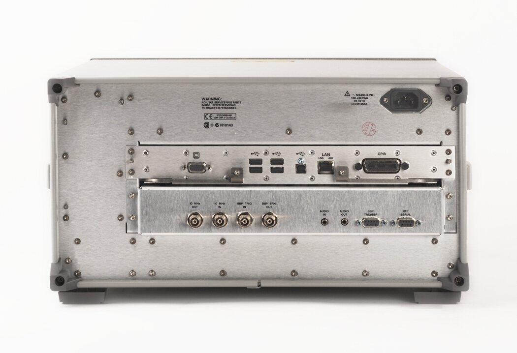
The test set's rear panel provides multiple connector types which are listed in this topic in alphabetical order.
Click on the connectors in the picture to learn more about them.
This BNC connector accepts an external 10 MHz timebase signal.
Input Frequency: 10 MHz ± locking range for internal timebase
Input Level Range: typically 0 to +10 dBm
Input Impedance: typically 50 ohms
This BNC connector provides a 10 MHz timebase signal to external test equipment.
Output Frequency: 10 MHz +/- locking range for internal timebase
Output Level Range: typically 0 to +10 dBm
Output Impedance: typically 50 ohms
Not functional for this release.
Not functional for this release.
This DB-9 connector allows five triggers for format dependent synchronization to external equipment. This connector is bi-directional. It is protected and provides and accepts TTL level pulses.
This BNC connector allows format dependent synchronization to external equipment. The connector is protected and accepts TTL level pulses.
This BNC connector allows format dependent synchronization of external equipment. The connector is protected and provides TTL level pulses.
This IEEE Standard 488.2 GPIB connector allows test set control with compatible devices.
The RJ45 connector allows for network connectivity. For example, it can be used for firmware updates, and remote desktop connection allowing the test set to be controlled by a PC.
This DB-15 connector allows you to simultaneously route the test set's display to another monitor. The resolution of the monitor must be set to the same as that of the front panel display which is 1024x768 with a refresh rate of 60 Hz.
100-240 Vac, 50-60 Hz, 260 W maximum
Not functional for this release.
USB-A: There are four rear panel Hi-Speed USB connectors for use with high-speed products (480 Mbps). In addition, there are two front panel USB connectors for use with slower speed products (1.5 Mbps and 12 Mbps). Use the universal serial bus (USB) connectors to connect USB devices to the test set (for example, mouse, keyboard, external storage device).
USB-B: There is one USB-B connector. This connector can be used by an external control program to control the test set over the USB. If you are using the test set as the controller, it is also possible for the test set to control itself over the USB. To do this connect a USB between the test set's USB-B connector and one of the four rear panel USB-A connectors. (Note, it is recommended that you use the rear panel USB-A connectors rather than the two front panel USB-A connectors.)
You can connect or disconnect USB devices without shutting down or restarting
the test set. Note that before you disconnect a USB device, you need to
inform Windows that you are ejecting, removing, or unplugging it, by using
the Safely Remove Hardware item  in the notification area. (The notification area is located
at the far right of the taskbar.)
in the notification area. (The notification area is located
at the far right of the taskbar.)
Note, the test set may not turn on if a USB storage device is connected to one of the USB connectors, therefore ensure that any USB storage devices are disconnected before turning on the test set.
Related Topic: Front Panel Features