This chapter contains an overview of the following software and programming tools:
Keysight M3201A/M3202A PXIe AWGs, M3100A/M3102A PXIe Digitizers, and M3300A/M3302A PXIe AWG/Digitizer Combos can be operated as classical bench-top instruments using Keysight SD1 SFP software; no programming is required.
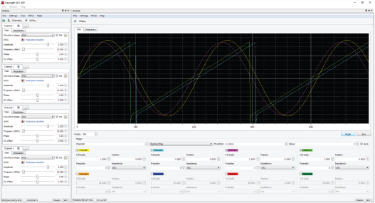
When SD1 SFP is opened, it identifies all Keysight PXIe hardware modules that are connected to the embedded controller or desktop computer, and opens a corresponding soft front panel for each piece of hardware.
|
|
||
| SD1 SFP |
The following programming tools are available to control Keysight M3100A/M3102A PXIe Digitizers, M3201A/M3202A PXIe AWGs, and M3300A/M3302A PXIe AWG & Digitizer Combinations:
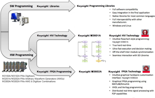
Keysight supplies a comprehensive set of highly optimized software instructions that can control off-the-shelf functionalities of Keysight hardware. These software instructions are compiled into the Keysight SD1 Programming Libraries. Programs can be written with these libraries and run on an embedded controller or desktop computer.
The use of customizable software to create user-defined control, test and measurement systems is commonly referred as Virtual Instrumentation. In Keysight documentation, the concept of a Virtual Instrument (or VI) describes user software that uses programming libraries and is executed by a computer.
Keysight provides native programming libraries for a comprehensive set of programming languages, such as C, C++, Visual Studio (VC++, C#, VB), MATLAB, National Instruments LabVIEW, Python, etc., ensuring full software compatibility and seamless multivendor integration. Keysight also provides dynamic libraries, for example: DLLs, that can be used in virtually any programming language.
Keysight native programming libraries ensure full compatibility, providing effortless and seamless software integration user interaction, etc. The I/O modules run in parallel, completely synchronized, and exchange data and decisions in real-time. The result is a set of modules that behave like a single integrated real-time instrument.
For more information, refer to the following sections:
Keysight M3201A/M3202A PXIe AWGs and M3100A/M3102A PXIe digitizer must have Option HV1 to use Keysight M3601A software; Option HV1 is only available at time of purchase.
Because the Keysight M3201A and M3202A PXIe AWGs have different output latencies, triggering both at the same time from HVI will always result in a 65 to 70 ns offset between their outputs.
The following section is only an overview of the Keysight M3601A software; To learn how to use Keysight M3601A software, refer to the User's Guide for the [3] Keysight M3601A Hard Virtual Instrument (HVI) Design Environment Software.
Keysight’s HVI technology provides the capability to create time-deterministic execution sequences that are executed by the Keysight M3201A/M3202A PXIe AWGs and M3100A/M3102A PXIe digitizers with Option HV1. HVIs are programmed with Keysight M3601A, an HVI design environment with a user-friendly flowchart-style interface.
Keysight’s HVI Technology uses the same programming instructions that are available in the Keysight SD1 Programming Libraries, with the difference that in an HVI, those instructions are executed by the hardware modules in hard real-time, not by the embeded controller or desktop computer.
Virtual Instrumentation is the use of customizable software and modular hardware to create user-defined measurement systems, called Virtual Instruments (VIs). Thus, a Virtual Instrument is based on a software which is executed by a computer, and therefore its real-time performance (speed, latency, etc.) is limited by the computer and by its operating system. In many cases, this real-time performance might not be enough for the application, even with a real-time operating system. In addition, many modern applications require tight triggering and precise intermodule synchronization, making the development of final systems very complex and time consuming. For all these applications, Keysight has developed an exclusive technology called Hard Virtual Instrumentation. In a hard virtual instrument (HVI), the user application is executed by the hardware modules independently of the computer, which stays free for other VI tasks, like visualization.
HVIs are programmed with Keysight M3601A Hard Virtual Instrument (HVI) Design Environment Software, with a user-friendly flowchart-style interface, compatible with Keysight M3201A/M3202A PXIe AWGs and M3100A/M3102A PXIe digitizers.

|
||
| M3601A | ||
|
Keysight M3601A is based on flowchart programming, providing an easy-to-use environment to develop hard real-time applications. |

Keysight M3601A Hard Virtual Instrument (HVI) Design Environment Software provides:
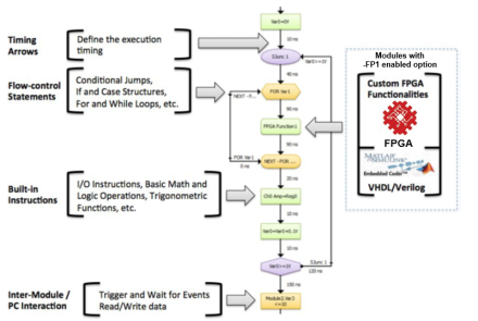
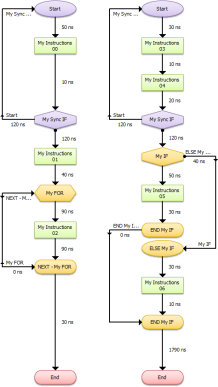
In an HVI, all Keysight modules run in parallel and completely synchronized, executing one flowchart per module. This results in simpler systems without the need of triggers.
Keysight FPGA programming technology is managed with Keysight M3602A FPGA Design Environment Software, an intuitive graphical FPGA programming environment.
Keysight M3201A/M3202A PXIe AWGs and M3100A/M3102A PXIe digitizers must have Option FP1 to use Keysight M3602A software; Option FP1 is only available at time of purchase.
The following section is only an overview of the Keysight M3602A software; To learn how to use Keysight M3602A software, refer to the User's Guide for the Keysight M3602A FPGA Design Environment Software.
Some applications require the use of custom on-board real-time processing which might not be covered by the comprehensive off-the-shelf functionalities of standard hardware products. For these applications, Keysight supplies Option FP1 (Enabled FPGA Programming), that provide the capability to program the on-board FPGA.
All Keysight M3201A/M3202A PXIe AWGs and M3100A/M3102A PXIe digitizers can add Option FP1, which provide the same built-in functionalities of their standard counterparts, giving the users more time to focus on their specific functionalities. For example, using Option FP1 on a Keysight M3100A/M3102A PXIe digitizer, the user has all the off-the-shelf functionalities of the hardware (data capture, triggering, etc.), but custom real-time FPGA processing can be added in the data path, between the acquisition and the transmission of data to the computer.

|
||
| M3602A | ||
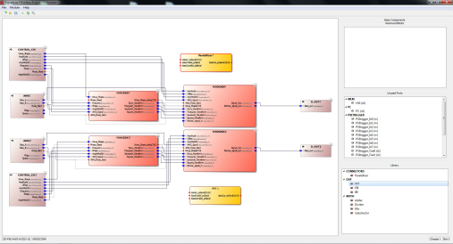
Keysight M3602A is a complete FPGA programming environment that allows the user to customize Keysight M3201A/M3202A PXIe AWGs and M3100A/M3102A PXIe digitizers with Option FP1. Keysight M3602A provides the necessary tools to design, compile, and program the FPGA of the module.
Graphical environment without performance penalty
Projects: MATLAB/Simulinkin conjunction with Xilinx
System Generator for DSP provides a powerful tool to implement digital signal processing. The user can go from the design/simulation power of MATLAB/Simulink to M3602A code in just a few clicks.
Add and remove built-in resources to free up space: The user can remove unused built-in resources to free up more FPGA space.

Keysight FPGA technology allows the user to customize Keysight M3201A/M3202A PXIe AWGs and M3100A/M3102A PXIe digitizers with Option FP1; these products are delivered with all the off-the-shelf functionalities of the standard products, and therefore the development time is dramatically reduced. The user can focus exclusively on expanding the functionality of the standard instrument, instead of developing a complete new one.
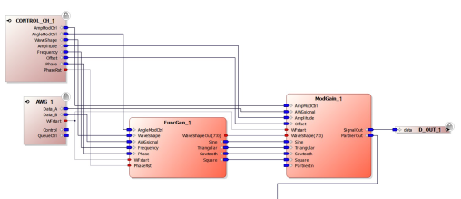
In Keysight M3602A, FPGA code is represented as boxes (called blocks) with IO ports. An empty project contains the ”Default Product Blocks” (off-the-shelf functionalities), and the ”Design IO Blocks” that provide the outer interface of the design. The user can add/remove blocks from the Keysight Block Library, External Blocks, or Xilinx IP cores.
Keysight M3602A provides up to x3 faster FPGA compiling and hot programming without having to reboot the system.
This block provides all the control parameters set by the user software using the
Keysight SD1 Programming Libraries.
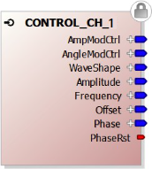
| Name | Description |
|---|---|
| Outputs | |
| AngleModCtrl | Angle modulation control (frequency or phase) |
| AmpModCtrl | Amplitude modulation control |
| WaveShape | Selects the output waveform |
| Amplitude | Signal amplitude value |
| Offset | DC offset value |
| Frequency | Signal frequency value |
| Phase | Signal phase value |
| PhaseRst | Signal to reset the phase of the function generator |
This block is the Dual Arbitrary Waveform Generator.
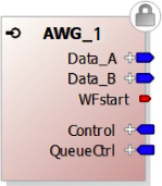
| Name | Description |
|---|---|
| Inputs | |
| Control | AWG operation control |
| QueueCtrl | AWG queue control |
| Outputs | |
| Data_A | Waveform A output (for dual waveforms), main waveform for single waveforms |
| Data_B | Waveform B output (for dual waveforms only) |
| WFstart | Signal that indicates when the AWG starts a waveform |
This block is a function generator with angle modulation capabilities.
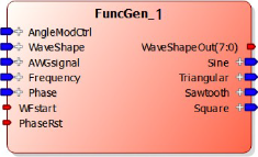
| Name | Description |
|---|---|
| Inputs | |
| AngleModCtrl | Configures the angle modulation (frequency or phase) |
| WaveShape | Selects the output waveform between Sine, Triangular or Square |
| AWGsignal | Arbitrary waveform coming from the AWG. It is used as the modulating signal |
| Frequency | Signal frequency value |
| Phase | Signal phase value |
| WFstart | Signal that indicates when the AWG signal starts a waveform |
| PhaseRst | Signal to reset the phase of the function generator |
| Outputs | |
| WaveShapeOut | Indicates which of the output signals is valid |
| Sine | Sinusoidal waveform |
| Triangular | Triangular waveform |
| Sawtooth | Not used |
| Square | Square waveform |
This block has the following functionalities:
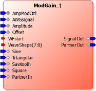
| Name | Description |
|---|---|
| Inputs | |
| AmpModCtrl | Configures the amplitude modulator |
| WaveShape | Selects the output waveform between: Sine, Triangular, Square, Partner Channel, or AWG |
| WFstart | Signal that indicates when the AWGsignal starts a waveform |
| Amplitude | Signal amplitude value |
| OffsetDC | offset value |
| Sine | Sinusoidal waveform coming from the Function Generator |
| Triangular | Triangular waveform coming from the Function Generator |
| Sawtooth | Not used |
| Square | Square waveform coming from the Function Generator |
| PartnerIn | Waveform coming from the Partner Channel. Used only in odd channels |
| AWGsignal | Arbitrary waveform coming from the AWG. It can be routed to SignalOut, or it can be used as the modulating signal |
| Outputs | |
| SignalOut | Output signal |
| PartnerOut | Copy of the output signal used for the even Partner Channel. |
This block sends the data directly to the hardware analog output.
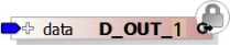
| Name | Description |
|---|---|
| Inputs | |
| data | data to be sent to the analog output channel |