Flowcharts represent a program or execution sequence by means of instructions and flow-control boxes (called statements), and timing arrows. Statements define HVI actions, while arrows define the execution flow and timing. All these elements are explained throughout this section.
Timing Arrows define and inform about the time between statements. Therefore, the user may thing as if statements do not take any time and all the timing information is given by the Timing Arrows. There are two kind of arrows:
Flow-control statements are elements that control the HVI execution flow. Synchronized Flow-Control Statements are particular Flow- control Statements that are executed in all modules at the same time.
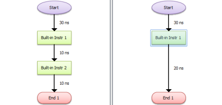
Every flowchart begins with a Start Statement (Figure 3), which is in fact a Synchronized Junction Statement (Figure 4), This statement ensures that all the hardware modules in an HVI start the execution fully synchronized.
The End Statement indicates the end of the HVI execution, and must be placed by the user to terminate the HVI properly (Figure 3).
A Synchronized Junction Statement is an element that can be used as a destination for conditional jumps (Synchronized Conditional).
Figure 3: Flowcharts of two modules, showing the Start and the End Statements
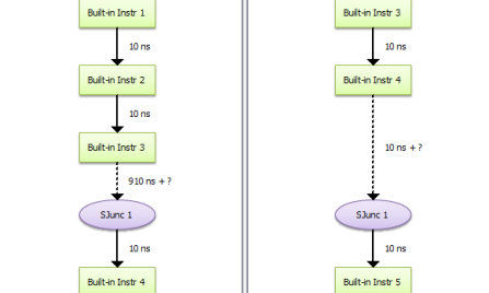
Figure 4: A Synchronized Junction Statement (ellipse-shaped element) can also be used to synchronize flowcharts
M3601A allows the user to perform conditional jumps to control the HVI execution flow, enabling the implementation of ultra-fast decision making, loops, etc.
A synchronized jump in the execution flow requires two elements:
The latter can be the statement right below the conditional or a Junction Statement placed anywhere in the flowchart (Figure 5).
Master and slave synchronized conditionals: In a Synchronized Conditional Statement, the decision is taken by only one of the modules (called master), and all the others (slaves) will comply with the same conditional result.
Flow-control Statements are elements that control the HVI execution flow. Local Flow-Control Statements are particular Flow-control Statements that are executed only in one module, without affecting the execution flow of other modules.
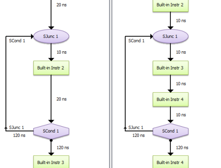
Figure 5: A Synchronized Conditional Statement (diamond-shaped element) jumps to a Junction Statement (ellipse-shaped element) in two modules exactly at the same time. The GUI maintains the synchronization by adjusting automatically the time of the last Timing Arrow. The solid dot in the arrow below the Conditional indicates the jump under a FALSE condition evaluation, while the side branch indicates the jump under a TRUE condition evaluation.
The If Block Statement is the classical ”if/else structure” available in any programming language. The If Block provides two operation options:
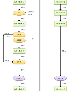
Figure 6: An If Block with equal timing in both branches does not desynchronize
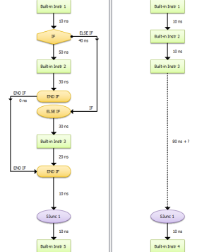
Figure 7: An If Block with different timing in both branches desynchronizes, as it it shown in the flowchart of the other modules (right)
The For Block Statement is the classical ”for loop structure” of any programming language. The user can choose which local register (M3601A HVI Design Environment Basics) is used for the loop index, and the exit value (number of loops).
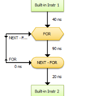
Figure 8: For Block Statement
A While Block Statement is the classical ”while loop” structure of any programming language. The execution loops while a condition is fulfilled.
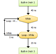
Figure 9: While Block Statement
The Wait Statement can be configured to wait for two different events:
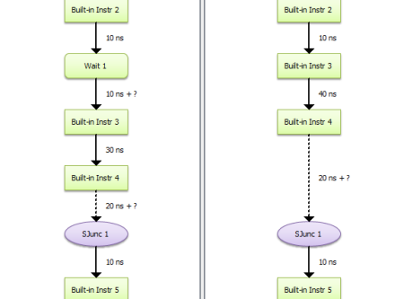
Figure 10: Wait Statement with an undefined execution time (left flowchart). This timing uncertainty can be seen in the arrow below the Wait. Please note that this also produces a desynchronization, which is shown with the dashed arrows above the Synchronized Junction. The latter performs a synchronization recovery in both modules (left and right).
Instruction statements describe the main actions of an HVI, without altering the execution flow directly.
Built-in instructions are the main execution statements of an HVI. There are two kind of instructions statements: module-specific, e.g. an instruction to change the amplitude of an Arbitrary Waveform Generator (AWG) (built-in module-specific instructions are described in the User Guide of the module), and universal instruction statements, like arithmetic operations, etc., which are available in all Keysight compatible modules with -HV1 programming enabled option.
Instruction Execution Latency: Instructions are triggered according to the statement timing within the flowchart, however each module-specific instruction has its own execution latency. Check the module datasheet for latency values.
This chapter describes the universal instruction statements available in all modules.
This function copies the value of the source parameter (S) into the destination variable (D).
Parameters
| Name | Description |
|---|---|
| Inputs | |
| Destination | Destination local register |
| Source |
Source value to be assigned:
· Source local register
|
This function subtracts, adds, multiplies or divides the values of the operands A and B, writing the result in R.
Parameters
| Name | Description |
|---|---|
| Inputs | |
| Result | Destination local register |
| A | First operand of the arithmetic operation:
· Constant in the specified format (Decimal, Binary, Hexadecimal, etc.) · Source local register · Module-specific digital values |
| Operation | Arithmetic operation (+, -, *, /) |
| B | Second operand of the arithmetic operation:
· Constant in the specified format (Decimal, Binary, Hexadecimal, etc.) · Source local register · Module-specific digital values |
This function performs a logic operation with the values of the operands A and B, writing the result in R.
Parameters
| Name | Description |
|---|---|
| Inputs | |
| Result | Destination local register |
| A | First operand of the operation:
· Constant in the specified format (Decimal, Binary, Hexadecimal, etc.) · Source local register · Module-specific digital values |
| Operation | Logic operation (and, or, xor, etc.) |
| B | Second operand of the operation:
· Constant in the specified format (Decimal, Binary, Hexadecimal, etc.) · Source local register · Module-specific digital values |
This function performs the square of the source parameter (A), writing the result in R.
Parameters
| Name | Description |
|---|---|
| Inputs | |
| Destination | Destination local register |
| A | Source value to be assigned:
· Constant in the specified format (Decimal, Binary, Hexadecimal, etc.) · Source local register · Module-specific digital values |
This function performs a read or write operation on port HVI available in M3602A.
Parameters
| Name | Description |
|---|---|
| Inputs | |
| Port | Port index of HVI port |
| Operation | Defines if it’s a read or write operation |
| Address | Offset from HVI port base address expressed in double words |
| Source | (Available only on write operation) Source value to be write on HVI port |
| Destination | (Available only on read operation) Destination local register |
Module-specific instructions are explained in the user guides of the corresponding hardware modules.
This statement writes or reads into/from a variable of another module (M3601A HVI Design Environment Basics).