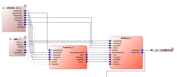
After hardware has been set up using the dialog box (see section 1.2.4), the associated hardware project for the card is opened. The contents of the software window will reflect the factory default functionalities of the hardware module.
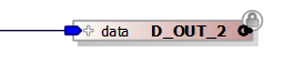
For example, here is the functionality of an AWG hardware module. To the left side of the image are two input port blocks: Control_CH_1 and AWG_1. To the right side of the image is an output port block: DOUT_1.
The icons to the far left of the input port blocks and far right of the output port block show the direction of the port signal. At these input and output ports are images of a locked padlock. This signifies that these ports cannot be removed from project. However, their connections can be edited. They have been designed to communicate with the module hardware.
|
|
These ports and blocks are represented by the gray (hardware ports) and brown (hardware blocks) icons in Keysight M3602A Design Environment.htm
In the modules above, different connector types can be identified. There are red connectors and blue connectors. Red connectors represent ports, and blue connectors represent interfaces. An interface is a set of ports.
The interfaces available for the hardware module are listed in the Ports section of the Hardware Components to the right side of the project window. To add them to the design, drag and drop them into the project window. Once in place, they can be configured and connected to other blocks within the project.
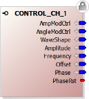
Here is an example of one of the project blocks.
Blocks have ports and interfaces. It can be seen from above that this block has inputs to the left (connectors pointing into the block), and outputs to the right side of the block (connectors out of the block).
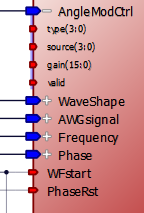
This block has three ports (red connectors), and the other connectors are interfaces (blue connectors). The ports can represent one bit of data or a vector of bits. If the port represents a vector of bits, size can be identified next to its name. In the example block above, there are two ports with one bit,“WFstart” and "PhaseRst.” The third port, “WaveShapeOut”, has a width of 8-bits, where next to its name the “(7:0)” notation is seen. This notation describes its bit ordering, where bit 7 is the most significant bit, and bit 0 is the least significant bit.
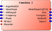
When clicking on the "+" sign of an interface, such as “AngleModctrl” in the above image, the internal ports of the interface appear shown below. Notice also that the “+” sign has changed to a “-“ sign. Clicking on the “-“ sign hides the ports again.
When the interface “AngleModctrl” is connected to another interface, the internal ports are also connected. Although these cannot normally be seen, the individual internal connections between the interface ports are connected. Please, keep in mind that the internal interface ports are connected while their parent interface is connected. Each interface knows how it has to be connected. The internal connections between ports are made automatically, the user only needs to connect the different interfaces and not worry about how it is done internally.
There are input ports and output ports.
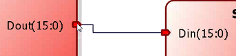
The input ports can only have one connection to an output port. Here Din(15:0) has one connection
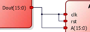
The output ports can be connected to many input ports. Here Dout(15:0) output is connected to three inputs.
An integer represents a source of data, so works as another output port. For this reason, integers can only be connected to input ports.
Adding an integer signal to an input port.
With the mouse, click on the input port, and click on "Connect to literal" as shown below.
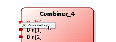
An integer box automatically appears. This can be edited to put in binary, hex or decimal to produce fixed value signals.
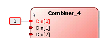
This technique can be applied to more than one input ports, such as to Din[1] and Din[2] above.
Interfaces with the same type can be connected. Therefore, interfaces of like protocols can be put together with a single connection.
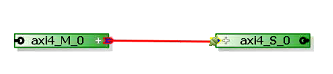
Clicking on the "+" sign for either interface the number and naming of the ports will be the same. By connecting the interface to interface, as shown above, all the ports shown are connected, one to one for each interface. This removes the chore of having to connect each interface port as shown below.
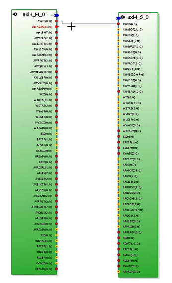
Interfaces can have two unique roles, one role is termed a Master, and the other role is termed a Slave. The Master interface can be connected to a Slave interface with the same type and vice versa. A Master interface controls the connected Slave interface.