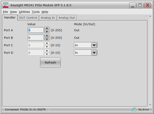
Value sets the value for output ports and shows the value for input ports
Mode (In/Out) The ports A and B are output only. The ports C and D are bidirectional. When Port C and D are assigned as an output port, value can be set.
A slash (/) symbol preceding signal names means that they are negative logic (active low).
Pin No. |
Signal Name |
Input/Output |
Description |
IVI |
1 |
GND |
N/A |
Ground. |
N/A |
2 |
/INPUT1 |
Input |
When this port receives a negative pulse, /OUTPUT1 and /OUTPUT2 are changed to the Low level. |
KtM9341HandlerIO.Input |
3 |
/OUTPUT1 |
Output |
Changes to the Low level when /INPUT1 receives a negative pulse. A command can be available for altering the Low/High level logic. |
KtM9341HandlerIO.Ouputs |
4 |
/OUTPUT2 |
Output |
Changes to the Low level when /INPUT1 receives a negative pulse. A command can be available for altering the Low/High level logic. |
KtM9341HandlerIO.Ouputs |
5 |
/PORT A0 |
Output |
Bit 0 of port A (8 bit parallel output port) |
IKtM9341HandlerIO.PortA |
6 |
/PORT A1 |
Output |
Bit 1 of port A (8 bit parallel output port) |
IKtM9341HandlerIO.PortA |
7 |
/PORT A2 |
Output |
Bit 2 of port A (8 bit parallel output port) |
IKtM9341HandlerIO.PortA |
8 |
/PORT A3 |
Output |
Bit 3 of port A (8 bit parallel output port) |
IKtM9341HandlerIO.PortA |
9 |
/PORT A4 |
Output |
Bit 4 of port A (8 bit parallel output port) |
IKtM9341HandlerIO.PortA |
10 |
/PORT A5 |
Output |
Bit 5 of port A (8 bit parallel output port) |
IKtM9341HandlerIO.PortA |
11 |
/PORT A6 |
Output |
Bit 6 of port A (8 bit parallel output port) |
IKtM9341HandlerIO.PortA |
12 |
/PORT A7 |
Output |
Bit 7 of port A (8 bit parallel output port) |
IKtM9341HandlerIO.PortA |
13 |
/PORT B0 |
Output |
Bit 0 of port B (8 bit parallel output port) |
IKtM9341HandlerIO.PortB |
14 |
/PORT B1 |
Output |
Bit 1 of port B (8 bit parallel output port) |
IKtM9341HandlerIO.PortB |
15 |
/PORT B2 |
Output |
Bit 2 of port B (8 bit parallel output port) |
IKtM9341HandlerIO.PortB |
16 |
/PORT B3 |
Output |
Bit 3 of port B (8 bit parallel output port) |
IKtM9341HandlerIO.PortB |
17 |
/PORT B4 |
Output |
Bit 4 of port B (8 bit parallel output port) |
IKtM9341HandlerIO.PortB |
/EXTERNAL TRIGGER |
Input |
This input is pass-through to the SMB sync 2 port. |
N/A |
|
19 |
/PORT B5 |
Output |
Bit 5 of port B (8 bit parallel output port) |
IKtM9341HandlerIO.PortB |
The pin function can be selected by the command of IKtM9341HandlerIO.IndexState |
||||
/PORT B6 |
Output |
Bit 6 of port B (8 bit parallel output port) |
IKtM9341HandlerIO.PortB |
|
/INDEX |
Output |
The input of SMB sync 3 port is pass-through to this port. |
N/A |
|
The pin function can be selected by the command of IKtM9341HandlerIO.ReadyForTriggerState |
||||
/PORT B7 |
Output |
Bit 7 of port B (8 bit parallel output port) |
IKtM9341HandlerIO.PortB |
|
/READY FOR TRIGGER |
Output |
The input of SMB sync 1 port is pass-through to this port. |
N/A |
|
22 |
/PORT C0 |
Input/Output |
Bit 0 of port C (4 bit parallel I/O port) |
IKtM9341HandlerIO.PortC |
23 |
/PORT C1 |
Input/Output |
Bit 1 of port C (4 bit parallel I/O port) |
IKtM9341HandlerIO.PortC |
24 |
/PORT C2 |
Input/Output |
Bit 2 of port C (4 bit parallel I/O port) |
IKtM9341HandlerIO.PortC |
25 |
/PORT C3 |
Input/Output |
Bit 3 of port C (4 bit parallel I/O port) |
IKtM9341HandlerIO.PortC |
26 |
/PORT D0 |
Input/Output |
Bit 0 of port D(4 bit parallel I/O port) |
IKtM9341HandlerIO.PortD |
27 |
/PORT D1 |
Input/Output |
Bit 1 of port D(4 bit parallel I/O port) |
IKtM9341HandlerIO.PortD |
28 |
/PORT D2 |
Input/Output |
Bit 2 of port D(4 bit parallel I/O port) |
IKtM9341HandlerIO.PortD |
29 |
/PORT D3 |
Input/Output |
Bit 3 of port D(4 bit parallel I/O port) |
IKtM9341HandlerIO.PortD |
30 |
PORT C STATUS |
Output |
Port C status signal. This signal is changed to the High level when the port C is configured to output port. It is changed to the Low level when the port is configured to input port. |
IKtM9341HandlerIO.PortCMode |
31 |
PORT D STATUS |
Output |
Port D status signal. This signal is changed to the High level when the port D is configured to output port. It is changed to the Low level when the port is configured to input port. |
IKtM9341HandlerIO.PortDMode |
32 |
/WRITE STROBE |
Output |
A output port write strobe signal. When data is present (that is, output level changes) on any of the output ports, this signal provides a negative pulse. |
N/A |
33 |
/PASS FAIL |
Output |
This output can be set by the command manually as the limit test function is not available on the M9341A/B standalone usage. |
IKtM9341HandlerIO.PassFail |
34 |
/SWEEP END |
Output |
This output can be set by the command manually as the sweep is not available on the M9341A/B standalone usage |
IKtM9341HandlerIO.GenerateSweepEndPulse |
35 |
+5V |
Output |
Provides +5V DC power supply for external instruments. |
N/A |
36 |
/PASS FAIL STROBE |
Output |
Each pass/fail results write a strobe signal. When /PASS FAIL is changed, this signal provides a negative pulse. |
N/A |
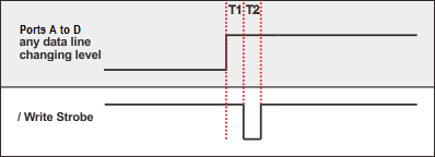
T1 = 1 μms : Write Strobe response time
T2 = 1 μms : Write Strobe pulse width
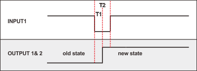
T1 = 0.1 μms : Output1 and 2 response time
T2 = 0.1 μms : Input1 Strobe pulse width
All Material Handler I/O Input and Output lines are TTL compatible. Input and
Lines carrying information IN (or bidirectional) to the VNA from the material handler.
Maximum Input Voltages: |
-0.5 V to 5.5 V |
TTL High level: |
2.0 V to 5.0 V |
TTL Low level: |
0 V to 0.5 V |
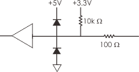 |
To Handler I/O Port |
Lines carrying information OUT of the VNA to the material handler.
Maximum Output Current: |
-10 mA to 10 mA |
|
Output Current |
TTL High level: |
-5 mA |
TTL Low level: |
3 mA |
|
Output Voltage |
TTL High level: |
2.0 V to 3.3 V |
TTL Low level: |
0 V to 0.8 V |
|
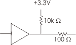 |
To Handler I/O Port |