Connector routing is supported only on the M9484C. Connector routing is used to associate the physical connectors to features of signal generation.
For the M9484C, Trigger Connectors can be used for routing as input or output. The available connectors are based on the instrument’s channels and options:
For channel 1 without Option AN1, and channels 2, 3, or 4, the connectors are:
Trig 1, Trig 2, Trig 3
For channel 1 with Option AN1 the connectors are:
Trig 1, Trig A, Trig B, Trig C, and AIO 1 through AIO 12
Connectors Trig A, Trig B, Trig C output bandwidth is limited to 100 MHz; when they are set for output, 3.3 V is the high voltage
Connectors AIO 1 through AIO 12 the input bandwidth is limited to 1 MHz
Via SCPI the connectors are referenced by a number; 1 to the maximum number of connectors. A SCPI command can be used to provide the connector label for the corresponding number.
|
SCPI Command |
:ROUTe[:CONNectors][:RF<channel>]:TRIG<connector>:LABel? |
|
SCPI Example |
ROUT:CONN:RF1:TRIG1:LABel? |
|
Notes |
The query result will be the labels on the front or rear panel of the instrument. The return value is a string that may contain whitespace characters; for example “Trig A”. For M9484C: For Channel 1 without Option AN1, and channels 2, 3, 4: 1 = “Trig 1” 2 = “Trig 2” 3 = “Trig 3” For Channel 1 with Option AN1: 1 = “Trig 1” 4 = “Trig A” 5 = “Trig B” 6 = “Trig C” 7 = “AIO 1” 8 = “AIO 2” … 18 = “AIO 12”
It is recommended that you do not query the connector labels for the specific options of the instrument. Attempting to query the label of a connector will raise error -200,”Execution Error”. See Query Options per Channel. |
|
Dependencies |
RF1:TRIG1|4|5|6|7|8|9|10|11|12|13|14|15|16|17|18 are available connectors when Option AN1 is present. RF1 available connectors without Option AN1 are TRIG[1]|2|3. RF2|3|4 available connectors are TRIG[1]|2|3. Attempting to send TRIG<number> for connectors that don’t exist on the instrument will generate an Execution Error |
|
State Saved |
N/A |
|
Initial S/W Revision |
A.09.00 |
Supported only on the M9484C.
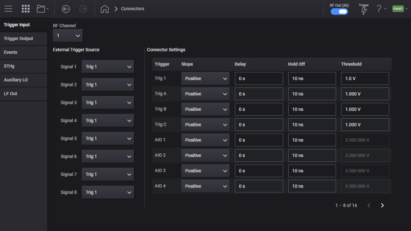
The physical trigger connectors can be used as inputs or outputs. As trigger inputs their operation is applicable when the Configuration Group for the channel is Independent. When the Configuration Group is not Independent see Global Trigger. For instruments with Option 8SG the trigger input can be directed to each Signal.
When a trigger connector is used as an input, the following settings can be configured.
For the M9484C, sets the polarity of the signal input at the channel’s trigger connector.
|
SCPI Command |
:ROUTe[:CONNectors][:RF<channel>]:TRIG<connector>:INPut:SLOPe POSitive|NEGative :ROUTe[:CONNectors][:RF<channel>]:TRIG<connector>:INPut:SLOPe? |
|
SCPI Example |
ROUT:CONN:RF1:TRIG1:INP:SLOP NEG ROUT:CONN:RF1:TRIG1:INP:SLOP? |
|
Notes |
Attempting to send TRIG<number> for connectors that don’t exist on the instrument will generate an Execution Error. |
|
Preset |
POSitive |
|
Range |
Negative | Positive |
|
State Saved |
Yes |
|
Initial S/W Revision |
A.09.00 |
For the M9484C, sets the input delay of a trigger connector.
|
SCPI Command |
:ROUTe[:CONNectors][:RF<channel>]:TRIG<connector>:INPut:DELay timeSec :ROUTe[:CONNectors][:RF<channel>]:TRIG<connector>:INPut:DELay? |
|
SCPI Example |
ROUT:CONN:RF1:TRIG1:INP:DEL 5 us ROUT:CONN:RF1:TRIG1:INP:DEL? |
|
Notes |
Attempting to send TRIG<number> for connectors that don’t exist on the instrument will generate an Execution Error. |
|
Preset |
0 s |
|
State Saved |
Yes |
|
Min |
0 s |
|
Max |
6.825 us |
|
Resolution |
1.666… ns |
|
Initial S/W Revision |
A.09.00 |
For the M9484C, sets the minimum time after an edge trigger before the system can perceive the next edge trigger. A trigger edge during this time period will be lost. This feature helps avoid double-triggering with a noisy or “bouncing” input signal.
|
SCPI Command |
:ROUTe[:CONNectors][:RF<channel>]:TRIG<connector>:INPut:HOLDoff timeSec :ROUTe[:CONNectors][:RF<channel>]:TRIG<connector>:INPut:HOLDoff? |
|
SCPI Example |
ROUT:CONN:RF1:TRIG1:INP:HOLD 2 s ROUT:CONN:RF1:TRIG1:INP:HOLD? |
|
Notes |
Attempting to send TRIG<number> for connectors that don’t exist on the instrument will generate an Execution Error. |
|
Preset |
10 ns |
|
State Saved |
Yes |
|
Min |
10 ns |
|
Max |
3.5 s |
|
Resolution |
1.666… ns |
|
Initial S/W Revision |
A.09.00 |
For the M9484C, sets the level above/below which the input signal is considered high vs low. Some connectors have fixed threshold levels.
For instruments that have Trig2 and Trig3, the threshold is fixed at 1.8 V CMOS.
For instruments that have AIO1 through AIO12, the threshold is fixed at 3.3 V CMOS.
|
SCPI Command |
:ROUTe[:CONNectors][:RF<channel>]:TRIG<connector>:INPut:THReshold <voltage> :ROUTe[:CONNectors][:RF<channel>]:TRIG<connector>:INPut:THReshold? |
|
SCPI Example |
ROUT:CONN:RF1:TRIG:INP:THR 1.5 V ROUT:CONN:RF1:TRIG:INP:THR? |
|
Notes |
Attempting to send TRIG<number> for connectors that don’t exist on the instrument will generate an Execution Error. Attempting to change value of TRIG<number> for connectors that have fixed values will generate an error. |
|
Preset |
1 V |
|
State Saved |
Yes |
|
Min |
Trig1: 0.5 V Trig2, Trig3: 1.8 V (Fixed) Trig4, Trig5, Trig6: 0.5 V Trig7 – Trig 18: 3.3 V (Fixed) |
|
Max |
Trig1: 2.5 V Trig2, Trig3: 1.8 V (Fixed) Trig4, Trig5, Trig6: 5 V Trig7 – Trig 18: 3.3 V (Fixed) |
|
Resolution |
Trig1: 100 mV Trig4, Trig5, Trig6: 9.765625 mV |
|
State Saved |
Yes |
|
Initial S/W Revision |
A.09.00 |
Supported only on the M9484C.
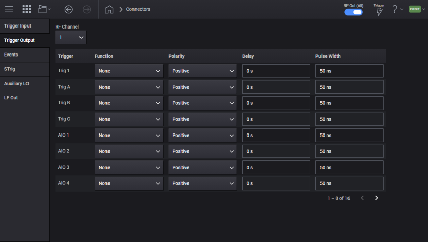
The physical trigger connectors can be used as inputs or outputs. When a trigger connector is used as an output, the following settings can be configured.
For the M9484C, routes a signal to a trigger connector for output.
Output routing options:
None (NONE) - No signals are routed to the connector. The connector may be an input.
Source Settled (SETTled) – Signals that the RF output is settled (frequency, phase, and amplitude are all within specification).
Event 1-3 (EVENt1|EVENt2|EVENt3) – Monitor the signal output on one of the Event outputs. The toggle rate will be 300 MHz maximum (3.333... ns) and the resolution will be 600 MHz (1.666... ns).
|
SCPI Command |
:ROUTe[:CONNectors][:RF<channel>]:TRIG<connector>:OUTPut NONE|SETTled|EVENt<1-3> :ROUTe[:CONNectors][:RF<channel>]:TRIG<connector>:OUTPut? |
|
SCPI Example |
ROUT:CONN:RF1:TRIG1:OUTP EVEN1 ROUT:CONN:RF1:TRIG1:OUTP? |
|
Notes |
Attempting to send TRIG<number> for connectors that don’t exist on the instrument will generate an Execution Error |
|
Couplings |
If the specified connector was being used as an input by any feature, then the trigger input type for those feature(s) is set to Trigger Key and a Settings Conflict error message is generated. |
|
Preset |
NONE |
|
Range |
None | Source Settled | Event1 | Event2 | Event3 |
|
State Saved |
Yes |
|
Initial S/W Revision |
A.09.00 |
For the M9484C, sets the polarity of the signal output at the trigger connector.
|
SCPI Command |
:ROUTe[:CONNectors][:RF<channel>]:TRIG<connector>:OUTPut:POLarity POSitive|NEGative :ROUTe[:CONNectors][:RF<channel>]:TRIG<connector>:OUTPut:POLarity? |
|
SCPI Example |
ROUT:CONN:RF1:TRIG1:OUTP:POL POS ROUT:CONN:RF1:TRIG1:OUTP:POL? |
|
Notes |
Attempting to send TRIG<number> for connectors that don’t exist on the instrument will generate an Execution Error. |
|
Preset |
POSitive |
|
Range |
Negative | Positive |
|
State Saved |
Yes |
|
Initial S/W Revision |
A.09.00 |
For the M9484C, sets the output delay of a trigger connector, its value is independent of any other delays applied to the signal being output.
|
SCPI Command |
:ROUTe[:CONNectors][:RF<channel>]:TRIG<connector>:OUTPut:DELay timeSec :ROUTe[:CONNectors][:RF<channel>]:TRIG<connector>:OUTPut:DELay? |
|
SCPI Example |
ROUT:CONN:RF1:TRIG1:OUTP:DEL 5 us ROUT:CONN:RF1:TRIG1:OUTP:DEL? |
|
Notes |
Attempting to send TRIG<number> for connectors that don’t exist on the instrument will generate an Execution Error. |
|
Preset |
0 s |
|
State Saved |
Yes |
|
Min |
0 s |
|
Max |
6.825 us |
|
Resolution |
1.666… ns |
|
Initial S/W Revision |
A.09.00 |
For the M9484C, sets the minimum duration of the trigger output level, helping make sure that outputs are wide enough in time to trigger external equipment. Note: If the trigger event transitions to inactive and back to active during the initial width, that event is lost and does not extend the width.
|
SCPI Command |
:ROUTe[:CONNectors][:RF<channel>]:TRIG<connector>:OUTPut:WIDTh timeSec :ROUTe[:CONNectors][:RF<channel>]:TRIG<connector>:OUTPut:WIDTh? |
|
SCPI Example |
ROUT:CONN:RF1:TRIG1:OUTP:WIDT 5 s ROUT:CONN:RF1:TRIG1:OUTP:WIDT? |
|
Notes |
Attempting to send TRIG<number> for connectors that don’t exist on the instrument will generate an Execution Error. |
|
Preset |
50 ns |
|
State Saved |
Yes |
|
Min |
10 ns |
|
Max |
7 s |
|
Resolution |
1.666… ns to double precision |
|
Initial S/W Revision |
A.09.00 |
Supported only on the M9484C.
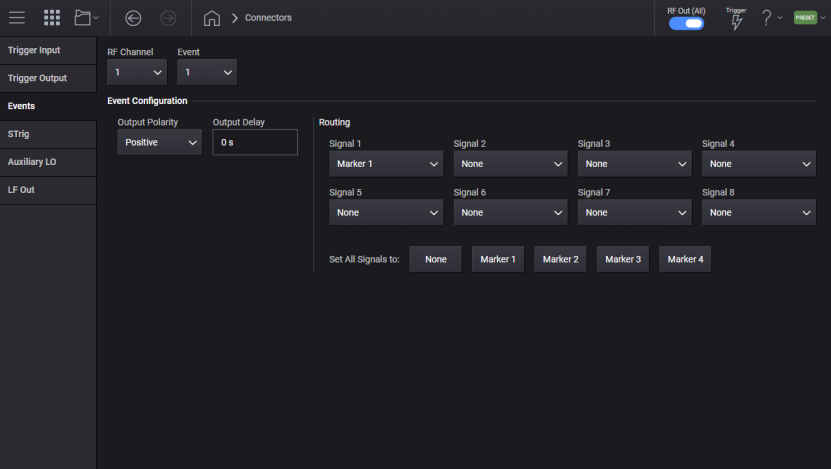
These three, output-only connectors have precise timing (at 3 GHz) for markers on baseband signals. The maximum rate of change is 600 MHz. If an Event output is configured to change too quickly, the output will only change on 600 MHz boundaries, regaining the proper level and precise timing wherever the rate of change is 600 MHz or less.
For the M9484C, Event connector routing can output markers from one or more signals, given the following criteria:
For each connector, only one marker can be selected from each signal.
Only per-signal marker selections for a connector can be ORed together. Note: If any are asserted, the output is asserted.
Per-signal marker selections cannot be combined with None or the single uniform Marker for all signals.
Event routing options:
None (NONE) - The connector is off.
Signal Marker Source(S<s>M<m>) - The Event output is asserted when the marker m from signal s is asserted. If more than one signal/marker combination is selected, then if any of them are asserted the connector output is asserted. Only one marker can be chosen from any one signal, so the list of marker selections is limited to the number of signals.
|
SCPI Command |
:ROUTe[:CONNectors][:RF<channel>]:EVENt{1:3} NONE|M1|M2|M3|M4|signalMarkerSource1[,signalMarkerSource2,…[,signalMarkerSource<signalCount>]] :ROUTe[:CONNectors][:RF<channel>]:EVENt{1:3}? signalMarkerSource<n>=S1M1|S2M1|…|S8M4 |
|
SCPI Example |
ROUT:CONN:RF1:EVEN1 S1M2 ROUT:CONN:RF1:EVEN1 S1M1,S2M1,S3M2 ROUT:CONN:RF1:EVEN1? |
|
Notes |
This SCPI command is not additive; sending it clears the Event’s previous output routing and sets them only to the options contained in the command. Additive tweaking of the Event’s output routing can be done manually on the front panel display. Querying the event will return the sorted order of the list of signalMarkerSource items selected. |
|
Preset |
Event1: S1M1 Event2: S1M2 Event3: S1M3 |
|
Range |
None | Marker1 | Marker2 | Marker3 | Marker4 | Signal Marker Source<n> |
|
State Saved |
Yes |
|
Initial S/W Revision |
A.09.00 |
For the M9484C, sets the polarity of the signal output at the channel’s event connector.
|
SCPI Command |
:ROUTe[:CONNectors][:RF<channel>]:EVENt{1:3}:POLarity POSitive|NEGative :ROUTe[:CONNectors][:RF<channel>]:EVENt{1:3}:POLarity? |
|
SCPI Example |
ROUT:CONN:RF1:EVEN1:POL NEG ROUT:CONN:RF1:EVEN1:POL? |
|
Preset |
POSitive |
|
Range |
Negative | Positive |
|
State Saved |
Yes |
|
Initial S/W Revision |
A.09.00 |
For the M9484C, sets the output delay at the channel’s event connector, its value is independent of any other delays applied to the signal being output.
|
SCPI Command |
:ROUTe[:CONNectors][:RF<channel>]:EVENt{1:3}:DELay timeSec :ROUTe[:CONNectors][:RF<channel>]:EVENt{1:3}:DELay? |
|
SCPI Example |
ROUT:CONN:RF1:EVEN1:DEL 50 ns ROUT:CONN:RF1:EVEN1:DEL? |
|
Preset |
0 s |
|
State Saved |
Yes |
|
Min |
0 s |
|
Max |
32.3958333333333 ns |
|
Resolution |
52.0833… ps |
|
Initial S/W Revision |
A.09.00 |
|
Modified S/W Revision |
A.10.00 Max value changed to 32.3958333333333 ns |
For M9484C with Option AL2.
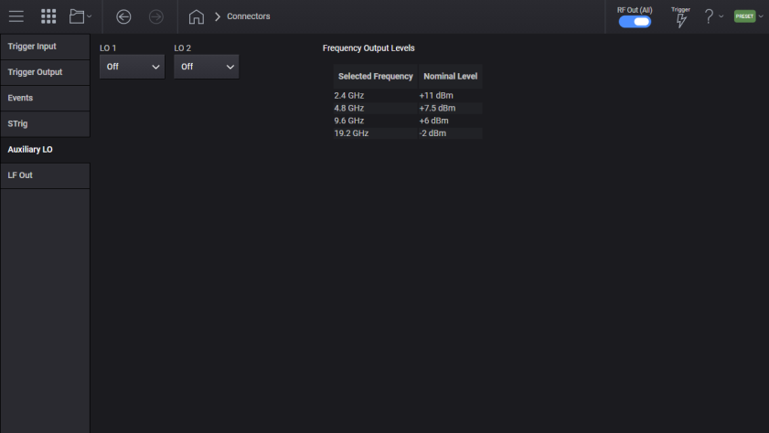
For M9484C with option AL2. The instrument contains two connectors labeled LO1 and LO2 for providing an Auxiliary Local Oscillator output. Each connector can be off, or provide a CW frequency of 2.4 GHz, 4.8 GHz, 9.6 GHz, or 19.2 GHz. If you are not using the output, place the setting in off to minimize emissions.
When using V3080A, the Auxiliary LO connector(s) are used for interfacing with V3080A. With a V3080A connected the auxiliary LO port is set to 9.6 GHz and not changeable. When one V3080A is connected to the instrument the LO1 will be used, if a second V3080A is connected LO2 will be used.
|
SCPI Command |
:ROUTe[:CONNectors]:ALOScillator[1]|2 OFF|F2_4|F4_8|F9_6|F19_2 :ROUTe[:CONNectors]:ALOScillator[1]|2? |
|
SCPI Example |
ROUT:ALOS2 F9_6 |
|
Notes |
If Option AL2 is not present, attempting to change ALOS raises error 703,"Feature not supported; Auxiliary LO unavailable on this instrument" |
|
Couplings |
When one or more V3080A are in use the Auxiliary LO is set to 9.6 GHz, and not changeable. For the first V3080A detected ALOS1 will be set to 9.6 GHz, when a second V3080A is detected ALOS2 will be set to 9.6 GHz. Attempting to change the Auxiliary LO with V3080A connected will raise the error "-221, Settings conflict; cannot change Auxiliary LO with V3080A connected" |
|
Preset |
If no V3080As are connected both ALSO1 and ALSO2 are OFF. If one V3080A is connected: ALOS1 is F9_6 ALOS2 is OFF If two V3080As are connected both ALSO1 and ALSO2 are F9_6. |
|
State Saved |
Yes |
|
Initial S/W Revision |
A.11.50 |
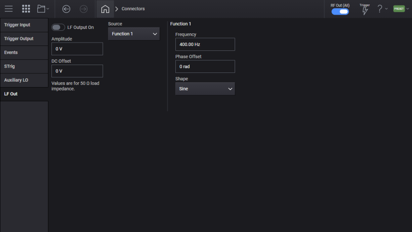
For M9484C with Option AN1.
LF Out, Low Frequency Output, is a connector that provides function generator capability. This function generator is independent of the RF Output.
Enables, or disables, the output on the LF Out connector.
|
SCPI Command |
[:SOURce][:RF<channel>]:LFOutput:STATe ON|OFF|1|0 [:SOURce][:RF<channel>]:LFOutput:STATe? |
|
SCPI Example |
LFO:STAT ON LFO:STAT? |
|
Notes |
For M9484C without option AN1, attempting to set the state on will raise the error 703, Feature not supported; LF Out State unavailable, option AN1 is required. For M9383B and M9384B, attempting to set state on will raise the error 703, Feature not supported; LF Out State unavailable on this instrument. |
|
Preset |
OFF |
|
State Saved |
Yes |
|
Initial S/W Revision |
A.11.50 |
This setting determines the amplitude of the signal at the LF Out connector. The total of DC Offset and amplitude cannot exceed the maximum amplitude value. If the source is DC, then only the DC Offset can be used. The value is for 50 Ohm load impedance.
|
SCPI Command |
[:SOURce][:RF<channel>]:LFOutput:AMPLitude <voltage> [:SOURce][:RF<channel>]:LFOutput:AMPLitude? |
|
SCPI Example |
LFO:AMPL 2V LFO:AMPL? |
|
Preset |
0 V |
|
State Saved |
Yes |
|
Min |
0 |
|
Max |
5 Vp |
|
Resolution |
0.001 V |
|
Initial S/W Revision |
A.11.50 |
This setting determines the DC Offset (in volts) of the signal at the LF Out connector. The total of DC Offset and amplitude cannot exceed the maximum amplitude value. If the source is DC, then only the DC Offset can be used. The value is for 50 Ohm load impedance.
|
SCPI Command |
[:SOURce][:RF<channel>]:LFOutput:OFFSet <voltage> [:SOURce][:RF<channel>]:LFOutput:OFFSet? |
|
SCPI Example |
LFO:OFFS -2V LFO:OFFS? |
|
Preset |
0 V |
|
State Saved |
Yes |
|
Min |
-5 V |
|
Max |
5 V |
|
Resolution |
0.001 V |
|
Initial S/W Revision |
A.11.50 |
This setting determines the source of the LF Out.
DC (DC) – Selects DC as the modulation source, which means that the LF Output DC Offset sets a continuous output voltage.
Function 1 (FUNCtion[1]) – Selects function generator 1 as the modulation source.
|
SCPI Command |
[:SOURce][:RF<channel>]:LFOutput:SOURce DC|FUNCtion[1] [:SOURce][:RF<channel>]:LFOutput:SOURce? |
|
SCPI Example |
LFO:SOUR DC LFO:SOUR? |
|
Preset |
FUNC1 |
|
State Saved |
Yes |
|
Initial S/W Revision |
A.11.50 |
Sets the frequency modulation rate for the waveform on the selected internal function generator.
|
SCPI Command |
[:SOURce][:RF<channel>]:LFOutput:FUNCtion[1]|2:FREQuency <frequency> [:SOURce][:RF<channel>]:LFOutput:FUNCtion[1]|2:FREQuency? |
|
SCPI Example |
LFO:FUNC:FREQ 30 LFO:FUNC:FREQ? |
|
Preset |
400 Hz |
|
State Saved |
Yes |
|
Min |
M9484C: 0.01 Hz |
|
Max |
1 MHz M9484C: 10 MHz |
|
Resolution |
M9484C: 0.01 Hz |
|
Initial S/W Revision |
A.11.50 |
Remote command only.
Sets the step increment for the internal frequency.
|
SCPI Command |
[:SOURce][:RF<channel>]:LFOutput:FREQuency:STEP[:INCRement] <frequency> [:SOURce][:RF<channel>]:LFOutput:FREQuency:STEP[:INCRement]? |
|
SCPI Example |
LFO:FREQ:STEP 10 KHZ LFO:FREQ:STEP? |
|
Dependencies |
Default value of 500 Hz is set by Restore System Defaults |
|
Preset |
500 Hz |
|
State Saved |
Persistent, survives preset and power cycle but not saved in the instrument state. |
|
Min |
M9484C: 0.01 Hz |
|
Max |
1 MHz |
|
Resolution |
M9484C: 0.01 Hz |
|
Initial S/W Revision |
A.11.50 |
Sets the phase offset (in radians) of the output. The value can be set in degrees as well via both GUI and SCPI.
|
SCPI Command |
[:SOURce][:RF<channel>]:LFOutput:FUNCtion[1]|2:POFFset <angle> [:SOURce][:RF<channel>]:LFOutput:FUNCtion[1]|2:POFFset? |
|
SCPI Example |
LFO:FUNC:POFF 2 LFO:FUNC:POFF? |
|
Preset |
0 |
|
State Saved |
Yes |
|
Min |
-6.29 rad |
|
Max |
6.29 rad |
|
Resolution |
0.001 rad |
|
Initial S/W Revision |
A.11.50 |
Sets the LF Output waveform type.
|
SCPI Command |
[:SOURce][:RF<channel>]:LFOutput:FUNCtion[1]|2:SHAPe SINE|TRIangle|PULSe|RAMP [:SOURce][:RF<channel>]:LFOutput:FUNCtion[1]|2:SHAPe? |
|
SCPI Example |
LFO:FUNC:SHAP SINE LFO:FUNC:SHAP? |
|
Preset |
SINE |
|
State Saved |
Yes |
|
Initial S/W Revision |
A.11.50 |
Remote command only.
Sets the ramp direction when :LFOutput:FUNCtion[1]|2:SHAPe is set to RAMP.
|
SCPI Command |
[:SOURce][:RF<channel>]:LFOutput:FUNCtion[1]|2:SHAPe:RAMP POSitive|NEGative [:SOURce][:RF<channel>]:LFOutput:FUNCtion[1]|2:SHAPe:RAMP? |
|
SCPI Example |
LFO:FUNC:SHAP:RAMP NEG LFO:FUNC:SHAP:RAMP? |
|
Preset |
POSitive |
|
State Saved |
Yes |
|
Initial S/W Revision |
A.11.50 |
Sets the duty cycle in percent for Pulse mode.
|
SCPI Command |
[:SOURce][:RF<channel>]:LFOutput:FUNCtion[1]|2:DCYCle <real> [:SOURce][:RF<channel>]:LFOutput:FUNCtion[1]|2:DCYCle? |
|
SCPI Example |
LFO:FUNC:DCYC 20 LFO:FUNC:DCYC? |
|
Preset |
50 |
|
State Saved |
Yes |
|
Min |
0 |
|
Max |
100 |
|
Resolution |
0.000000000001 |
|
Initial S/W Revision |
A.11.50 |