This capability requires license model N7653APPC.
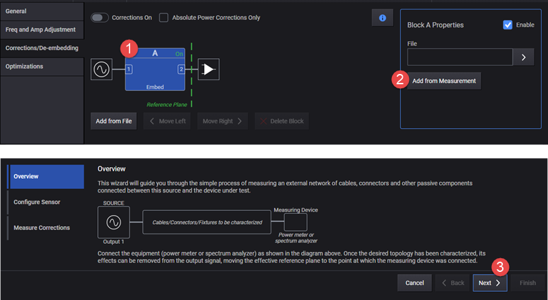
This topic describes the Corrections Setup screen, where you can configure and apply external corrections for your test setup. Blocks can be added from supported file formats (.s2p, .csv, .uflat) or by direct measurement, using one of the supported power sensors (power meter, spectrum analyzer, network analyzer). This area also updates to show your correction status.
Absolute Power Corrections Only
De-embedding is used to remove the effects of the test fixtures, including cabling from the measurement results. De-embedding uses a model of the test fixture and mathematically removes the fixture characteristics (cables, connectors and other passive components) between the source and the device under test (DUT). Once the desired topology has been characterized, its effects can be removed from the output signal, moving the effective reference plane to the point at which the power sensor was connected.
Blocks can be added from supported file formats (.s2p, .csv, .uflat) or by direct measurement, using one of the supported power sensors (power meter, spectrum analyzer, or a network analyzer).
Naming Convention
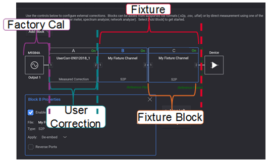
Factory Cal = Directly measured correction data applied from factory measurements.
User Correction = Directly measured correction data applied from user measurements on top or in place of the Factory Cal.
Fixture = Calculated correction data from a Cal Set file applied by the user on top of the User Correction and/or Factory Cal.
Fixture Block = Individual fixture blocks representing different fixture elements.
Cal Set = The cal set is a file used to perform the error correction.
Enables or disables the user-flatness corrections.
|
GUI Location |
RF Output > Corrections/De-embedding > Corrections On |
|
SCPI Command |
[:SOURce][:RF<channel>]:CORRection[:STATe] ON|OFF|1|0 [:SOURce][:RF<channel>]:CORRection[:STATe]? |
|
SCPI Example |
CORR ON CORR? |
|
Preset |
0 |
|
State Saved |
Yes |
|
Initial S/W Revision |
A.01.00 |
Ignores the complex response data in both measured and s2p data and only applies the absolute power corrections.
|
GUI Location |
RF Output > Corrections/De-embedding > Absolute Power Corrections On |
|
SCPI Command |
[:SOURce][:RF<channel>]:CORRection:APConly[:STATe] ON|OFF|0|1 [:SOURce][:RF<channel>]:CORRection:APConly[:STATe]? |
|
SCPI Example |
CORR:APC ON CORR:APC? |
|
Preset |
0 |
|
State Saved |
Yes |
|
Initial S/W Revision |
A.02.00 |
SCPI commands defined in this section can be used to set up Correction measurements and Power Sensors used. In the user interface, these settings are included in the RF Output block's, Corrections/De-embedding block setup, when the Add from Measurement button is selected.
Supported measurement devices are as follows.
Keysight U8480 Series USB Thermocouple Power Sensor
Keysight U2000 Series USB Sensors
Including:
U2000 Series USB Power Sensors
U8487A-CFG007
U8485A-CFG006
U2000A
U2001A
U2002A
U2004A
U2000B
U2001B
U2000H
U2001H
U2002H
X-Series Signal Analyzers:
N9000A/B
N9010A/B
N9020A/B
N9030A/B
N9040B
N9041B
M90XA
N9021B
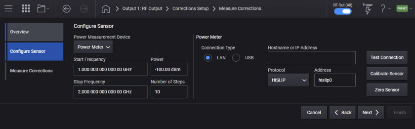
Selects the hardware type used in the user correction measurement.
PMETer: Flatness calibration is done with a power meter.
SANalyzer: Flatness calibration is done with a spectrum analyzer. Note that the reference clock must be locked between the VXG signal generator and the spectrum analyzer.
|
GUI Location |
RF Output > Corrections/De-embedding > Add from Measurement > Configure Sensor > Power Measurement Device |
|
SCPI Command |
[:SOURce][:RF<channel>]:CORRection:PMDevice PMETer|SANalyzer [:SOURce][:RF<channel>]:CORRection:PMDevice? |
|
SCPI Example |
CORR:PMD PMET CORR:PMD? |
|
Preset |
PMETer |
|
State Saved |
Yes |
|
Choices |
Power Meter | Spectrum Analyzer |
|
Initial S/W Revision |
A.01.00 |
Sets the start frequency for the user flatness calibration step array.
|
GUI Location |
RF Output > Corrections/De-embedding > Add from Measurement > Start Freq |
|
SCPI Command |
[:SOURce][:RF<channel>]:CORRection:FLATness:STEP:STARt <freq> [:SOURce][:RF<channel>]:CORRection:FLATness:STEP:STARt? |
|
SCPI Example |
CORR:FLAT:STEP:STAR 1GHz CORR:FLAT:STEP:STAR? |
|
Couplings |
Clipped to Stop Freq |
|
Preset |
1 GHz |
|
State Saved |
Yes |
|
Min |
For M9383B/M9384B = 1 MHz For M9384B with M1749A connected = 24.25 GHz For M9484C = 9 kHz |
|
Max |
For M9383B/M9384B: With Option F14 = 14 GHz With Option F20 = 20 GHz With Option F32 = 31.8 GHz With Option F44 = 44 GHz For M9384B with M1749A connected = 48.2 GHz For M9384B: With Option 506 = 6 GHz With Option 508 = 8.5 GHz With Option 514 = 14 GHz With Option 520 = 21.6GHz With Option 532 = 31.8 GHz With Option 544 = 44 GHz With Option 554 = 54 GHz |
|
Resolution |
For M9383B/M9384B: 0.01 Hz For M9484C: 0.00001 Hz |
|
Initial S/W Revision |
A.01.00 |
|
Modified S/W Revision |
A.09.00 |
|
History |
Added M9484C at A.09.00 |
Sets the stop frequency for the user flatness calibration step array.
|
GUI Location |
RF Output > Corrections/De-embedding > Add from Measurement > Stop Freq |
|
SCPI Command |
[:SOURce][:RF<channel>]:CORRection:FLATness:STEP:STOP <freq> [:SOURce][:RF<channel>]:CORRection:FLATness:STEP:STOP? |
|
SCPI Example |
CORR:FLAT:STEP:STOP 1GHz CORR:FLAT:STEP:STOP? |
|
Couplings |
Clipped to Start Freq |
|
Preset |
2 GHz |
|
State Saved |
Yes |
|
Min |
For M9383B/M9384B = 1 MHz For M9384B with M1749A connected = 24.25 GHz For M9484C = 9 kHz |
|
Max |
For M9383B/M9384B: With Option F14 = 14 GHz With Option F20 = 20 GHz With Option F32 = 31.8 GHz With Option F44 = 44 GHz For M9384B with M1749A connected = 48.2 GHz For M9384B: With Option 506 = 6 GHz With Option 508 = 8.5 GHz With Option 514 = 14 GHz With Option 520 = 21.6 GHz With Option 532 = 31.8 GHz With Option 544 = 44 GHz With Option 554 = 54 GHz |
|
Resolution |
For M9383B/M9384B: 0.01 Hz For M9484C: 0.00001 Hz |
|
Initial S/W Revision |
A.01.00 |
|
Modified S/W Revision |
A.09.00 |
|
History |
Added M9484C at A.09.00 |
Defines the number of points in the user flatness calibration step array.
|
GUI Location |
RF Output > Corrections/De-embedding > Add from Measurement > Num Steps |
|
SCPI Command |
[:SOURce][:RF<channel>]:CORRection:FLATness:STEP:POINts <integer> [:SOURce][:RF<channel>]:CORRection:FLATness:STEP: POINts? |
|
SCPI Example |
CORR:FLAT:STEP:POIN 2 CORR:FLAT:STEP:POIN? |
|
Preset |
10 |
|
State Saved |
Yes |
|
Min |
2 |
|
Max |
10000 |
|
Initial S/W Revision |
A.01.00 |
Sets the power meter properties when Power Meter is the selected Power Measurement Device.
Sets the type of control connection for communication using the external power meter for user flatness calibration.
|
VXI11 |
Enables the power meter for VXI-11 control through the signal generator. A power meter with GPIB can be controlled through VXI-11 using a LAN-GPIB gateway. |
|
HISLip |
Enables the power meter for HiSlip control through the signal generator |
|
SOCKets |
Enables the power meter for sockets LAN control through the signal generator. |
|
USB |
Enables the power meter for USB control through the signal generator. |
|
Initial S/W Revision |
A.01.00 |
The settings enabled by this command are not affected by a signal generator power-on, preset, or *RST.
|
GUI Location |
RF Output > Corrections/De-embedding > Add from Measurement > Configure > Connection Type > LAN, (Instrument VXI-11, HiSLIP, Socket) or USB |
|
SCPI Command |
[:SOURce][:RF<channel>]:CORRection:PMETer:COMMunicate:TYPE SOCKets|VXI11|USB|HISLip [:SOURce][:RF<channel>]:CORRection:PMETer:COMMunicate:TYPE? |
|
SCPI Example |
CORR:PMET:COMM:TYPE SOCK CORR:PMET:COMM:TYPE? |
|
Preset |
SOCKets |
|
State Saved |
No |
|
Choices |
Socket | VXI11 | USB | HiSlip |
|
Initial S/W Revision |
A.01.00 |
Sets the internet protocol (IP) address for a power meter that is controlled by the signal generator for user flatness calibration. If connecting to a GPIB power meter through a LAN-GPIB gateway, this command sets the IP address of the gateway.
The settings enabled by this command are not affected by signal generator power-on, preset, or *RST. Ensure that the power meter IP address is different from the signal generator address.
|
GUI Location |
RF Output > Corrections/De-embedding > Add from Measurement > Configure > Connection Type > Connection Type LAN > Set LAN Address |
|
SCPI Command |
[:SOURce][:RF<channel>]:CORRection:PMETer:COMMunicate:LAN:IP <string> [:SOURce][:RF<channel>]:CORRection:PMETer:COMMunicate:LAN:IP? |
|
SCPI Example |
CORR:PMET:COMM:LAN:IP "192.168.1.5" CORR:PMET:COMM:LAN:IP? |
|
State Saved |
No |
|
Initial S/W Revision |
A.01.00 |
Specifies the VXI-11 device name for a power meter that is being controlled by the signal generator for user flatness calibration. If connecting directly to the power meter, enter the name as specified on your power meter documentation. If connecting through a LAN-GPIB gateway, enter the SICL address of the power meter.
The settings enabled by this command are not affected by signal generator power-on, preset, or *RST.
|
GUI Location |
RF Output > Corrections/De-embedding > Add from Measurement > Configure > Connection Type > LAN > Instrument (VXI-11) > Remote Name |
|
SCPI Command |
[:SOURce][:RF<channel>]:CORRection:PMETer:COMMunicate:LAN:DEVice <string> [:SOURce][:RF<channel>]:CORRection:PMETer:COMMunicate:LAN:DEVice? |
|
SCPI Example |
CORR:PMET:COMM:LAN:DEV "instr0" CORR:PMET:COMM:LAN:DEV? |
|
Preset |
inst0 |
|
State Saved |
No |
|
Initial S/W Revision |
A.01.00 |
Specifies the HiSLIP device name for a power meter that is being controlled by the signal generator for user flatness calibration. If connecting directly to the power meter, enter the name as specified in your power meter documentation.
The settings enabled by this command are not affected by signal generator power-on, preset, or *RST.
|
GUI Location |
RF Output > Corrections/De-embedding > Add from Measurement > Configure > Connection Type LAN > HiSLIP > Remote Name |
|
SCPI Command |
[:SOURce][:RF<channel>]:CORRection:PMETer:COMMunicate:HISLip:DEVice <string> [:SOURce][:RF<channel>]:CORRection:PMETer:COMMunicate:HISLip:DEVice? |
|
SCPI Example |
CORR:PMET:COMM:HISL:DEV "hslip1" CORR:PMET:COMM:HISL:DEV? |
|
Preset |
hislip0 |
|
State Saved |
No |
|
Initial S/W Revision |
A.01.00 |
Selects the USB device to be used for user flatness calibration. The query returns the USB device identification.
The setting enabled by this command is not affected by signal generator power-on, preset, or *RST.
|
GUI Location |
RF Output > Corrections/De-embedding > Add from Measurement > Configure > Connection Type USB > Device |
|
SCPI Command |
[:SOURce][:RF<channel>]:CORRection:PMETer:COMMunicate:USB:DEVice <string> [:SOURce][:RF<channel>]:CORRection:PMETer:COMMunicate:USB:DEVice? |
|
SCPI Example |
CORR:PMET:COMM:USB:DEV "instr0" CORR:PMET:COMM:USB:DEV? |
|
State Saved |
No |
|
Initial S/W Revision |
A.01.00 |
Remote command only.
Returns a listing of all connected USB devices.
The setting enabled by this command is not affected by signal generator power-on, preset, or *RST.
|
SCPI Command |
[:SOURce][:RF<channel>]:CORRection:PMETer:COMMunicate:USB:LIST? |
|
SCPI Example |
CORR:PMET:COMM:USB:LIST? |
|
State Saved |
No |
|
Initial S/W Revision |
A.01.00 |
Sets the IP port number on the power meter that is controlled by the signal generator for users flatness calibration.
|
5025 |
Standard mode. The command enables standard mode for simple programming. |
|
5024 |
Telnet mode. The command enables the telnet SCPI service for programming. |
|
Initial S/W Revision |
A.01.00 |
The setting enabled by this command is not affected by signal generator power-on, preset, or *RST.
|
GUI Location |
RF Output > Corrections/De-embedding > Add from Measurement > Configure > Connection Type LAN > Socket Port Number |
|
SCPI Command |
[:SOURce][:RF<channel>]:CORRection:PMETer:COMMunicate:LAN:PORT <integer> [:SOURce][:RF<channel>]:CORRection:PMETer:COMMunicate:LAN:PORT? |
|
SCPI Example |
CORR:PMET:COMM:LAN:PORT 5025 CORR:PMET:COMM:LAN:PORT? |
|
Preset |
5025 |
|
State Saved |
No |
|
Initial S/W Revision |
A.01.00 |
Calibrates the connected power meter. This is an immediate action.
|
GUI Location |
RF Output > Corrections/De-embedding > Add from Measurement > Configure > Calibrate Sensor |
|
SCPI Command |
[:SOURce][:RF<channel>]:CORRection:PMETer:CALibrate |
|
SCPI Example |
CORR:PMET:CAL |
|
Initial S/W Revision |
A.01.00 |
Zeroes the connected power meter. This is an immediate action.
|
GUI Location |
RF Output > Corrections/De-embedding > Add from Measurement > Configure > Zero Sensor |
|
SCPI Command |
[:SOURce][:RF<channel>]:CORRection:PMETer:ZERO |
|
SCPI Example |
CORR:PMET:ZERO |
|
Initial S/W Revision |
A.01.00 |
Sets the spectrum analyzer properties when Spectrum Analyzer is the selected Power Measurement Device.
Sets the type of control connection for communication with the external spectrum analyzer for user flatness calibration.
|
VXI11 |
Enables the spectrum analyzer for VXI-11 control through the signal generator. A spectrum analyzer with GPIB can be controlled through VXI-11 using a LAN-GPIB gateway. |
|
HISLip |
Enables the spectrum analyzer for HiSlip control through the signal generator. |
|
SOCKets |
Enables the spectrum analyzer for sockets LAN control through the signal generator. |
|
USB |
Enables the spectrum analyzer for USB control through the signal generator. |
|
GUI Location |
RF Output > Corrections/De-embedding > Add from Measurement > Configure > Connection Type > LAN, (Instrument VXI-11, HiSLIP, Socket) or USB |
|
SCPI Command |
[:SOURce][:RF<channel>]:CORRection:SANalyzer:COMMunicate:TYPE SOCKets|VXI11|USB|HISLip [:SOURce][:RF<channel>]:CORRection:SANalyzer:COMMunicate:TYPE? |
|
SCPI Example |
CORR:SAN:COMM:TYPE SOCK CORR:SAN:COMM:TYPE? |
|
Notes |
The setting enabled by this command is not affected by signal generator power-on, preset, or *RST. |
|
Preset |
SOCKets |
|
State Saved |
No |
|
Choices |
Socket | VXI11 | USB | HiSlip |
|
Initial S/W Revision |
A.01.00 |
Sets the internet protocol (IP) address for a spectrum analyzer that is controlled by the signal generator for user flatness calibration. If connecting to a GPIB spectrum analyzer through a LAN-GPIB gateway, this command sets the IP address of the gateway.
|
GUI Location |
RF Output > Corrections/De-embedding > Add from Measurement > Configure > Connection Type > LAN > Set LAN Address |
|
SCPI Command |
[:SOURce][:RF<channel>]:CORRection:SANalyzer:COMMunicate:LAN:IP <string> [:SOURce][:RF<channel>]:CORRection:SANalyzer:COMMunicate:LAN:IP? |
|
SCPI Example |
CORR:SAN:COMM:LAN:IP "192.168.1.5" CORR:SAN:COMM:LAN:IP? |
|
Notes |
The setting enabled by this command is not affected by signal generator power-on, preset, or *RST. Ensure that the spectrum analyzer IP address is different from the signal generator address. |
|
State Saved |
No |
|
Initial S/W Revision |
A.01.00 |
Enter a VXI-11 device name for a spectrum analyzer that is being controlled by the signal generator for user flatness calibration. If connecting directly to the spectrum analyzer, enter the name as specified on your spectrum analyzer documentation. If connecting through a LAN-GPIB gateway, enter the SICL address of the spectrum analyzer.
|
GUI Location |
RF Output > Corrections/De-embedding > Add from Measurement > Configure > Connection Type > LAN > Instrument (VXI-11) > Remote Name |
|
SCPI Command |
[:SOURce][:RF<channel>]:CORRection:SANalyzer:COMMunicate:LAN:DEVice <string> [:SOURce][:RF<channel>]:CORRection:SANalyzer:COMMunicate:LAN:DEVice? |
|
SCPI Example |
CORR:SAN:COMM:LAN:DEV "instr0" CORR:SAN:COMM:LAN:DEV? |
|
Notes |
The setting enabled by this command is not affected by a signal generator power-on, preset, or *RST. |
|
Preset |
inst0 |
|
State Saved |
No |
|
Initial S/W Revision |
A.01.00 |
Enter a HiSlip device name for a spectrum analyzer that is being controlled by the signal generator for user flatness calibration. If connecting directly to the spectrum analyzer, enter the name as specified on your spectrum analyzer documentation.
|
GUI Location |
RF Output > Corrections/De-embedding > Add from Measurement > Configure > Connection Type > LAN > HiSLIP > Remote Name |
|
SCPI Command |
[:SOURce][:RF<channel>]:CORRection:SANalyzer:COMMunicate:HISLip:DEVice <string> [:SOURce][:RF<channel>]:CORRection:SANalyzer:COMMunicate:HISLip:DEVice? |
|
SCPI Example |
CORR:SAN:COMM:HISL:DEV "instr0" CORR:SAN:COMM:HISL:DEV? |
|
Notes |
The setting enabled by this command is not affected by signal generator power-on, preset, or *RST. |
|
Preset |
hislip0 |
|
State Saved |
No |
|
Initial S/W Revision |
A.01.00 |
Selects the USB device to be used for user flatness calibration. The query returns the USB device identification.
|
GUI Location |
RF Output > Corrections/De-embedding > Add from Measurement > Configure > Connection Type > USB > Device |
|
SCPI Command |
[:SOURce][:RF<channel>]:CORRection:SANalyzer:COMMunicate:USB:DEVice <string> [:SOURce][:RF<channel>]:CORRection:SANalyzer:COMMunicate:USB:DEVice? |
|
SCPI Example |
CORR:SAN:COMM:USB:DEV "instr0" CORR:SAN:COMM:USB:DEV? |
|
Notes |
The setting enabled by this command is not affected by signal generator power-on, preset, or *RST. |
|
State Saved |
No |
|
Initial S/W Revision |
A.01.00 |
Sets the spectrum analyzer's IP port number that is controlled by the signal generator for users flatness calibration.
|
GUI Location |
RF Output > Corrections/De-embedding > Add from Measurement > Configure > Connection Type > LAN > Set LAN Address |
|
5025 |
Standard mode. The command enables standard mode for simple programming. |
|
5024 |
Telnet mode. The command enables the telnet SCPI service for programming. |
|
SCPI Command |
[:SOURce][:RF<channel>]:CORRection:SANalyzer:COMMunicate:LAN:PORT <integer> [:SOURce][:RF<channel>]:CORRection:SANalyzer:COMMunicate:LAN:PORT? |
|
SCPI Example |
CORR:SAN:COMM:LAN:PORT 5025 CORR:SAN:COMM:LAN:PORT? |
|
Notes |
The setting enabled by this command is not affected by signal generator power-on, preset, or *RST. |
|
Preset |
5025 |
|
State Saved |
No |
|
Initial S/W Revision |
A.01.00 |
Remote command only.
Query only. Returns a listing of all connected USB devices.
|
SCPI Command |
[:SOURce][:RF<channel>]:CORRection:SANalyzer:COMMunicate:USB:LIST? |
|
SCPI Example |
CORR:SAN:COMM:USB:LIST? |
|
Notes |
The setting enabled by this command is not affected by signal generator power-on, preset, or *RST. |
|
State Saved |
No |
|
Initial S/W Revision |
A.01.00 |
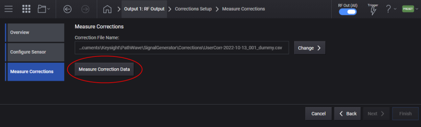
The measured correction data will be saved to the specified file. The file path can be either a full or a relative path. When a relative path is given as file path, it will be based on D:\Users\Instrument\Documents\Keysight\PathWave\SignalGenerator\Corrections. If no file is specified, a file name is automatically created.
This is an overlapped command that initiates the Correction Data measurement. The measurement can be aborted by the Abort command.
Note that the reference clock must be locked between the VXG signal generator and the spectrum analyzer.
|
GUI Location |
RF Output > Corrections/De-embedding > Add from Measurement > Measure Corrections > Measure Correction Data |
|
SCPI Command |
[:SOURce][:RF<channel>]:CORRection:FLATness:CALibrate [<file>] |
|
SCPI Example |
CORR:FLAT:CAL |
|
State Saved |
No |
|
Initial S/W Revision |
A.01.00 |
Aborts the Correction Data measurement.
|
GUI Location |
RF Output > Corrections/De-embedding > Add from Measurement > Measure Corrections > Abort |
|
SCPI Command |
[:SOURce][:RF<channel>]:CORRection:FLATness:CALibrate:ABORt |
|
SCPI Example |
CORR:FLAT:CAL:ABOR |
|
State Saved |
No |
|
Initial S/W Revision |
A.01.00 |
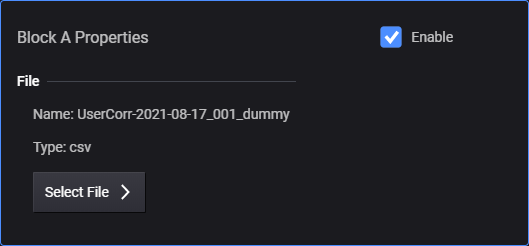
There are two types of block for Correction/De-embedding. User Correction is a block that is for measured correction data. This block comes next to the instrument RF output and always exists. The other block type is a Fixture Block, which consists of a Fixture between the instrument and DUT. There can be up to four Fixture Blocks in Corrections Setup. A Fixture Block can be dynamically configured using either Add, Move Left, Move Right, Delete, Clear, and Add SCPI commands or GUI functions.
To access Block Properties from the GUI, click on the applicable Block: Block A, Block B, Block C or Block D. Block A will always be present and is for User Corrections.
Displays or returns the number of Blocks configured for corrections. The maximum number of blocks is four. The minimum number is 1. The first block is for User Corrections and is always present.
|
GUI Location |
RF Output > Corrections/De-embedding |
|
SCPI Command |
[:SOURce][:RF<channel>]:CORRection:BLOCk:COUNt? |
|
SCPI Example |
CORR:BLOC:COUN? |
|
Initial S/W Revision |
A.01.00 |
Sets or queries the user-correction data file, which is stored in D:\Users\Instrument\Documents\Keysight\PathWave\SignalGenerator\Corrections.
For remote operation, if the data file format used is *.s2p or *.uflat then it can be set with a relative path to the Corrections folder. However, if the data file format used is *.csv, then an absolute path is required to set the data file.
|
GUI Location |
RF Output > Corrections/De-embedding > select applicable Block > Block Properties > Change File, current file name is displayed to the left of the button |
|
SCPI Command |
[:SOURce][:RF<channel>]:CORRection:BLOCk{1:4}:FILE <"file path"> [:SOURce][:RF<channel>]:CORRection:BLOCk{1:4}:FILE? |
|
SCPI Example |
CORR:BLOC:FILE "FixtureChannel2" |
|
State Saved |
Yes |
|
Initial S/W Revision |
A.01.00 |
Enables or disables the selected block.
|
GUI Location |
RF Output > Corrections/De-embedding > select applicable Block > Block Properties > Enable. |
|
SCPI Command |
[:SOURce][:RF<channel>]:CORRection:BLOCk{1:4}[:STATe] ON|OFF|1|0 [:SOURce][:RF<channel>]:CORRection:BLOCk{1:4}[:STATe]? |
|
SCPI Example |
CORR:BLOC 1 CORR:BLOC? |
|
State Saved |
Yes |
|
Initial S/W Revision |
A.01.00 |
Specifies how the data is applied to the cascaded correction data. When De-embed is selected, the output at the frequency point is adjusted to compensate for the amplitude and phase changes introduced by the block. When Embed is selected, it is adjusted to include them.
|
GUI Location |
RF Output > Corrections/De-embedding > select applicable Block > Block Properties > Apply Deembed or Embed |
|
SCPI Command |
[:SOURce][:RF<channel>]:CORRection:BLOCk{2:4}:APPLy DEEMbedding|EMBedding |
|
SCPI Example |
CORR:BLOC2:APPL EMB CORR:BLOC2:APPL? |
|
State Saved |
Yes |
|
Choices |
De-embed | Embed |
|
Initial S/W Revision |
A.01.00 |
Specifies whether the port is reversed or not.
|
GUI Location |
RF Output > Corrections/De-embedding > select applicable Block > Block Properties > Revers Ports |
|
SCPI Command |
[:SOURce][:RF<channel>]:CORRection:BLOCk{2:4}:RPORt ON|OFF|1|0 [:SOURce][:RF<channel>]:CORRection:BLOCk{2:4}:RPORt? |
|
SCPI Example |
CORR:BLOC2:RPOR 1 CORR:BLOC2:RPOR? |
|
State Saved |
Yes |
|
Initial S/W Revision |
A.01.00 |
Adds a fixture block at the end of blocks.
|
GUI Location |
RF Output > Corrections/De-embedding > Add from File |
|
SCPI Command |
[:SOURce][:RF<channel>]:CORRection:BLOCk:ADD:FIXTure <file>[,<apply>[,<rport>]] |
|
SCPI Example |
CORR:BLOC:ADD "data.s2p" |
|
State Saved |
No |
|
Initial S/W Revision |
A.01.00 |
Remote command only.
Clears all the blocks except for the first one. The first block is for User Correction and cannot be deleted from the list.
|
SCPI Command |
[:SOURce][:RF<channel>]:CORRection:BLOCk:CLEar:FIXTure |
|
SCPI Example |
CORR:BLOC:CLE:FIXT |
|
Initial S/W Revision |
A.01.00 |
Deletes the specified block. If the specified block doesn’t exist, it issues an error.
There is no SCPI command for this function.
|
GUI Location |
RF Output > Corrections/De-embedding > select applicable Block > Block Properties > Delete Block |
|
Initial S/W Revision |
A.01.00 |
Moves the specified block to the specified position. If the specified block doesn’t exist, it issues an error. If the destination block is smaller than the number of blocks, it issues an error.
There is no SCPI command for this function.
|
GUI Location |
RF Output > Corrections/De-embedding > select applicable Block > Block Properties > Move Left or Move Right |
|
Initial S/W Revision |
A.01.00 |