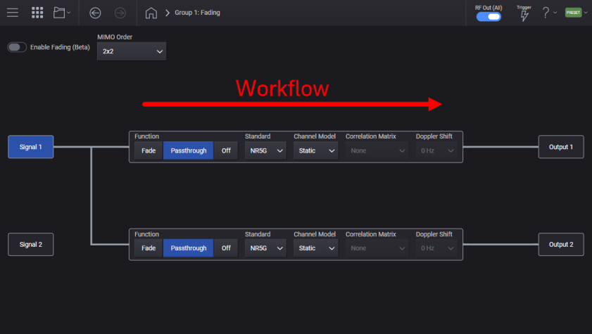
After selecting a channel configuration, waveform file (or real-time), and MIMO Order, the Fading graphical user-interface (GUI) presents you with a set of parameters for each signal path. The intended workflow progresses left to right, as available parameter selections are often dependent on what was selected prior (to left).
Enables or disables the fader processing for the specified Group. This control also appears on the Signal Summary screen.
|
GUI Location |
Signals > Signal Summary selection > Fading Setup > Enable Fading |
|
SCPI Command |
[:SOURce]:GROup<group>:FADing ON|OFF|1|0 [:SOURce]:GROup<group>:FADing? |
|
SCPI Example |
GRO:FAD ON GRO:FAD? |
|
Notes |
Setting cannot be set to On when license N7605AP0C is not present or the specified Group’s Configuration is not supported. Supported Configuration Modes are Independent and MIMO2. Attempts to set a value not allowed will generate error: -224,”Illegal parameter value” |
|
Preset |
OFF |
|
State Saved |
Yes |
|
Initial S/W Revision |
A.10.00 |
Specifies the desired number of signals within the specified Group to apply fading to. This is the N in NxM MIMO. This parameter also appears on the Signal Summary screen.
|
GUI Location |
Signals > Signal Summary selection > Fading Setup > MIMO Order |
|
SCPI Command |
[:SOURce]:GROup<group>:FADing:MORDer 1|2|4|8 [:SOURce]:GROup<group>:FADing:MORDer? |
|
SCPI Example |
GRO:FAD:MORD 1 GRO:FAD:MORD? |
|
Notes |
Setting cannot be changed without Option 8SG and license N7605AP0C. Attempts to set a value not allowed will generate error: -224,”Illegal parameter value” The value of this setting will affect the available options for Channel Model, Correlation Matrix, and Doppler Shifts. |
|
Preset |
1 |
|
State Saved |
Yes |
|
Initial S/W Revision |
A.10.00 |
Specifies the fader processing for the specified signal and RF Output. Selecting “FADE” will apply the selected fading profile to the specified fading path. Selecting “PASSthrough” will play the signal with no fading applied. Selecting “OFF” is equivalent to muting this signal path.
|
GUI Location |
Signals > Signal Summary selection > Fading Setup > Function |
|
SCPI Command |
[:SOURce]:GROup<group>:SIGNal<signal>:FADing<path>:FUNCtion FADE|PASSthrough|OFF [:SOURce]:GROup<group>:SIGNal<signal>:FADing<path>:FUNC? |
|
SCPI Example |
GRO:SIGN:FAD2:FUNC FADE ! This sets fading for the first signal in the first group’s output on the second RF Output. GRO:SIGN:FAD2:FUNC? |
|
Notes |
Fading (FADing SCPI command parameter) cardinality is based upon the channels configured in each group. |
|
Dependencies |
Note the group “Enable Fading” command supersedes this signal level fading function. If “Enable Fading” is not turned on for the group, the status of signal fading is ignored. |
|
Preset |
PASS |
|
Choices |
FADE | PASSthrough | OFF |
|
State Saved |
Yes |
|
Initial S/W Revision |
A.10.00 |
Selects the radio standard for the specified fader. The standard models cover propagation environments that allow you to test whether your device meets the performance requirements as defined by the respective standard.
|
GUI Location |
Signals > Signal Summary selection > Fading Setup > Standard |
|
SCPI Command |
[:SOURce]:GROup<group>:SIGNal<signal>:FADing<path>:STANdard NR5G|LTE [:SOURce]:GROup<group>:SIGNal<signal>:FADing<path>:STANdard? |
|
SCPI Example |
GRO:SIGN:FAD:STAN NR5G GRO:SIGN:FAD:STAN? |
|
Notes |
Fading (FADing SCPI command parameter) cardinality is based upon the channels configured in each group. |
|
Preset |
NR5G |
|
State Saved |
Yes |
|
Initial S/W Revision |
A.10.0 |
The channel model setting specifies the channel model (simulation type) for the specified fader. There are different models available for each standard. They are listed in more detail below.
A channel model is a mathematical representation of the effects of a communication channel through which wireless signals are propagated. The channel model can represent the power loss incurred by the signal as it travels through the wireless medium to the receiver.
|
GUI Location |
Signals > Signal Summary selection > Fading Setup > Channel Model |
|
SCPI Command |
[:SOURce]:GROup<group>:SIGNal<signal>:FADing<path>:CMODel STATic|TDLA30|TDLB100|TDLC60|TDLC300|HST1000|HST750|CQI112|CQI450|CQI|EPA|ETU|EVA|HST|MBSFN [:SOURce]:GROup<group>:SIGNal<signal>:FADing<path>:CMODel? |
|
SCPI Example |
GRO:SIGN:FAD:CMOD TDLA30 GRO:SIGN:FAD:CMOD? |
|
Notes |
Attempts to set a value not allowed for the current instrument configuration and standard will generate error: -224,”Illegal parameter value” Fading (FADing SCPI command parameter) cardinality is based upon the channels configured in each group. STATIC, TDLA30, TDLB100, TDLC60, TDLC300, HST1000, HST750, CQI112, CQI450 The models available for LTE are: STATIC, CQI, EPA, ETU, EVA, HST, MBSFN The HST1000 and HST750 (High Speed Train) channel models are suitable to model the behavior of a receiver on a high-speed train or more generally a fast-moving receiver passing a stationary transmitter. The CQI is the Channel Quality Indicator. The EPA (Extended Pedestrian A) channel model uses Rayleigh fading. The ETU (Extended Typical Urban) channel model uses Rayleigh fading. The MBSFN channel model is the Multicast-Broadcast Single-Frequency Networks channel model. |
|
Dependencies |
The set of allowed values depends upon the group configuration and standard. |
|
Preset |
STATIC |
|
Choices |
Static | TDLA30 | TDLB100 | TDLC60 | TDLC300 | HST1000 | HST750 | CQI112 | CQI450 | CQI | EPA | ETA | EVA | HST | MBSFN |
|
State Saved |
Yes |
|
Initial S/W Revision |
A.10.0 |
The correlation matrix setting specifies the correlation level in spatial paths to use between the RF Outputs in the instrument group. In general, the higher the correlation between channels, the worse the “channel disparity”. Because MIMO is banking on spatial differences in the channel to increase throughput, the higher correlated models represent worse conditions and subsequently lower throughput.
The correlation matrix settings are related to 3GPP standards. 5GNR base station conformance tests have correlations defined by 38.141-1 document in Annex G.
|
GUI Location |
Signals > Signal Summary selection > Fading Setup > Correlation Matrix |
|
SCPI Command |
[:SOURce]:GROup<group>:SIGNal<signal>:FADing<path>:CMATrix NONE|LOW|MEDIUM|MEDIUMA|HIGH|XPOLLOW|XPOLMEDIUM|XPOLMEDIUMA|XPOLHIGH [:SOURce]:GROup<group>:SIGNal<signal>:FADing<path>:CMATrix? |
|
SCPI Example |
GRO:SIGN:FAD:CMAT MEDIUMA GRO:SIGN:FAD:CMAT? |
|
Notes |
Attempts to set a value not allowed for the current instrument configuration and channel model will generate error: -224,”Illegal parameter value” Fading (FADing SCPI command parameter) cardinality is based upon the channels configured in each group. XPOL is an abbreviation for cross polarization. |
|
Dependencies |
The set of allowed values depends upon the group configuration and channel model. For single RF output group configurations, NONE is the only available selection. |
|
Preset |
NONE |
|
Choices |
None | Low | Medium | Medium A | High | X Pol Low | X Pol Medium | X Pol Medium A | X Pol High |
|
State Saved |
Yes |
|
Initial S/W Revision |
A.10.0 |
This parameter specifies the doppler shift for the given fader. Doppler shift describes the changes in frequency of a propagated wave produced by a moving source with respect to an observer. Waves transmitted by an object traveling toward an observer get compressed resulting in a higher frequency as the source approaches the receiver.
|
GUI Location |
Signals > Signal Summary selection > Fading Setup > Doppler Shift |
|
SCPI Command |
[:SOURce]:GROup<group>:SIGNal<signal>:FADing<path>:DSHift <freq> [:SOURce]:GROup<group>:SIGNal<signal>:FADing<path>:DSHift? |
|
SCPI Example |
GRO:SIGN:FAD:DSH 75 !Sets the fader doppler shift to 75 Hz GRO:SIGN:FAD:DSH? |
|
Notes |
Fading (FADing SCPI command parameter) cardinality is based upon the channels configured in each group. |
|
Dependencies |
The set of allowed values depends upon the group configuration, channel model, and correlation matrix. |
|
Preset |
0 Hz |
|
State Saved |
Yes |
|
Min |
0 |
|
Max |
The min, max and resolution are based upon the discrete values inside the fading profiles installed on the instrument. In other words, the actual value used will be quantized by the possibilities present. The preset value above is the doppler shift value in the “STATIC” channel model, which is the preset channel model. |
|
Initial S/W Revision |
A.10.0 |