Custom Modulation
Choices: Custom IQ
Select the custom modulation format of the waveform. The tree view nodes and associated properties in the parameter view change with each selection.
Custom IQ: Single carrier signal with user-defined IQ constellations.
|
SCPI Command |
[SOURce]:RADio:CMODulation:WAVeform:LVERsion:DATE:REQuired? |
|
SCPI Example |
|
|
Preset |
2023.0801 |
|
State Saved |
No |
|
Initial S/W Revision |
A.16.00 |
Enable or disable the User Defined Sample Rate. If enabled, the OverSamplingRatio will not be used.
|
SCPI Command |
[:SOURce]:RADio:CMODulation:WAVeform:SRATe:USER[:STATe] ON|OFF|1|0 [:SOURce]:RADio:CMODulation:WAVeform:SRATe:USER[:STATe]? |
|
SCPI Example |
|
|
Couplings |
|
| Choices | On | Off |
|
Preset |
Off |
|
State Saved |
Yes |
|
Initial S/W Revision |
A.14.00 |
User defined sample rate is not applicable for Radar signal.
Enter the oversampling ratio of the waveform. The Total Sample Points is automatically determined based on the oversampling ratio.
Oversampling Ratio is not applicable for Radar signal.
|
SCPI Command |
[:SOURce]:RADio:CMODulation:WAVeform:OSRatio <integer> [:SOURce]:RADio:CMODulation:WAVeform:OSRatio? |
|
SCPI Example |
|
|
Couplings |
|
|
Preset |
4 |
|
State Saved |
Yes |
|
Minimum Value |
2 |
|
Maximum Value |
1024 |
|
IVI Interface |
|
|
Initial S/W Revision |
A.14.00 |
Set the value of user defined sample rate if user defined sample rate is enabled.
|
SCPI Command |
[:SOURce]:RADio:CMODulation:WAVeform:SRATe <real> [:SOURce]:RADio:CMODulation:WAVeform:SRATe? |
|
SCPI Example |
|
|
Couplings |
|
|
Preset |
200000000 |
|
State Saved |
Yes |
|
Minimum Value |
100000 |
|
Maximum Value |
4000000000 |
|
Initial S/W Revision |
A.14.00 |
Enter the number of frames included in the waveform.
|
SCPI Command |
[:SOURce]:RADio:CMODulation:WAVeform:FRAMes:COUNt <integer> [:SOURce]:RADio:CMODulation:WAVeform:FRAMes:COUNt? |
|
SCPI Example |
|
|
Couplings |
|
|
Preset |
1 |
|
State Saved |
Yes |
|
Minimum Value |
1 |
|
Maximum Value |
300 |
|
Initial S/W Revision |
A.14.00 |
Displays the generated waveform length in sample points. This value is read-only and automatically updates with changes to oversampling ratio, number of frames, and custom modulation type.
|
SCPI Command |
[:SOURce]:RADio:CMODulation:WAVeform:SAMPles:COUNt? |
|
SCPI Example |
|
|
Couplings |
|
|
Preset |
4000 |
|
State Saved |
Yes |
|
Initial S/W Revision |
A.14.00 |
Displays the generated waveform length in seconds. This value is read-only and automatically updates with changes to oversampling ratio, number of frames, and custom modulation type.
|
SCPI Command |
[:SOURce]:RADio:CMODulation:WAVeform:LENGth? |
|
SCPI Example |
|
|
Couplings |
|
|
Preset |
0.001 |
|
State Saved |
Yes |
|
Initial S/W Revision |
A.14.00 |
Enable or disable the mirror spectrum (inverted IQ) for the waveform.
|
SCPI Command |
[:SOURce]:RADio:CMODulation:WAVeform:MIRRor:SPECtrum[:STATe] ON|OFF|1|0 [:SOURce]:RADio:CMODulation:WAVeform:MIRRor:SPECtrum[:STATe]? |
|
SCPI Example |
|
|
Couplings |
|
| Choices | On | Off |
|
Preset |
Off |
|
State Saved |
Yes |
|
Initial S/W Revision |
A.14.00 |
Choices: Waveform Start | Frame Start | RF Blanking Control | RF ALC Control
Default: Waveform Start
Select the source for marker 1.
Waveform Start: It indicates the beginning of the waveform.
Frame Start: It indicates the beginning of each frame in the waveform.
RF Blanking Control: It indicates the burst part in the waveform.
RF ALC Control: It indicates the part used for ALC control in the waveform.
|
SCPI Command |
[:SOURce]:RADio:CMODulation:WAVeform:M1Source WSTart|FSTart|ALC|BLANking [:SOURce]:RADio:CMODulation:WAVeform:M1Source? |
|
SCPI Example |
|
|
Couplings |
|
|
Preset |
WSTart |
|
State Saved |
Yes |
|
Initial S/W Revision |
A.14.00 |
Choices: Waveform Start | Frame Start | RF Blanking Control | RF ALC Control
Default: Frame Start
Select the source for marker 2.
Waveform Start: It indicates the beginning of the waveform.
Frame Start: It indicates the beginning of each frame in the waveform.
RF Blanking Control: It indicates the burst part in the waveform.
RF ALC Control: It indicates the part used for ALC control in the waveform.
|
SCPI Command |
[:SOURce]:RADio:CMODulation:WAVeform:M2Source WSTart|FSTart|ALC|BLANking [:SOURce]:RADio:CMODulation:WAVeform:M2Source? |
|
SCPI Example |
|
|
Couplings |
|
|
Preset |
FSTart |
|
State Saved |
Yes |
|
Initial S/W Revision |
A.14.00 |
Default: RF Blanking Control
Displays the source for marker 3. RF Blanking Control is always used as Marker 3 source.
|
SCPI Command |
[:SOURce]:RADio:CMODulation:WAVeform:M3Source? |
|
SCPI Example |
|
|
Couplings |
|
|
Range |
Value range is WSTart | FSTart | ALC | BLANking |
|
Preset |
BLANking |
|
State Saved |
Yes |
|
Initial S/W Revision |
A.14.00 |
Default: RF ALC Control
Displays the source for marker 4. RF ALC Control is always used as Marker 4 source.
|
SCPI Command |
[:SOURce]:RADio:CMODulation:WAVeform:M4Source? |
|
SCPI Example |
|
|
Couplings |
|
|
Range |
Value range is WSTart | FSTart |ALC | BLANking |
|
Preset |
ALC |
|
State Saved |
Yes |
|
Initial S/W Revision |
A.14.00 |
Enable or disable the crest factor reduction for the waveform. When enabled, peak cancellation algorithm is used to subtract a weighted version of the cancellation pulses from the original input signal. It strikes a balance between the out-of-band emission and in-band waveform quality when reducing the PAPR of the signal.
Crest Factor Reduction is always visible and configurable under Waveform Setup, however, supporting parameters appear only when Crest Factor Reduction is enabled. If the waveform PAPR is already lower than the target level, then no processing will be performed on the original waveform.
|
SCPI Command |
[:SOURce]:RADio:CMODulation:WAVeform:CFReduction[:STATe] ON|OFF|1|0 [:SOURce]:RADio:CMODulation:WAVeform:CFReduction[:STATe]? |
|
SCPI Example |
|
|
Couplings |
|
|
Preset |
Off |
|
State Saved |
Yes |
| Choices | On | Off |
| Default Value | Off |
|
Initial S/W Revision |
A.14.00 |
Set the PAPR value to achieve after crest factor reduction.
|
SCPI Command |
[:SOURce]:RADio:CMODulation:WAVeform:CFReduction:PAPR <real> [:SOURce]:RADio:CMODulation:WAVeform:CFReduction:PAPR? |
|
SCPI Example |
|
|
Couplings |
|
|
Preset |
8 |
|
State Saved |
Yes |
|
Minimum Value |
3 dB |
|
Maximum Value |
100 dB |
|
Default Value |
8 dB |
|
Initial S/W Revision |
A.14.00 |
Specify the maximum times of iteration. With the increasing of iteration, the PAPR value should converge to a steady level.
|
SCPI Command |
[:SOURce]:RADio:CMODulation:WAVeform:CFReduction:MITeration <integer> [:SOURce]:RADio:CMODulation:WAVeform:CFReduction:MITeration? |
|
SCPI Example |
|
|
Couplings |
|
|
Preset |
10 |
|
State Saved |
Yes |
|
Minimum Value |
1 |
|
Maximum Value |
20 |
|
Default Value |
10 |
|
Initial S/W Revision |
A.14.00 |
Specify the percentage that the cancellation pulses can be removed.
|
SCPI Command |
[:SOURce]:RADio:CMODulation:WAVeform:CFReduction:CPERcent <real> [:SOURce]:RADio:CMODulation:WAVeform:CFReduction:CPERcent? |
|
SCPI Example |
|
|
Couplings |
|
|
Preset |
100 |
|
State Saved |
Yes |
|
Minimum Value |
0 |
|
Maximum Value |
100 |
|
Default Value |
100 |
|
Initial S/W Revision |
A.14.00 |
Block is the range that a single cancellation pulse can be identified. If the waveform length is L, and the block size is B, then the number of blocks is N=floor(L/B)+1. Therefore, there will be N pulses at most to be removed.
|
SCPI Command |
[:SOURce]:RADio:CMODulation:WAVeform:CFReduction:BSIZe <integer> [:SOURce]:RADio:CMODulation:WAVeform:CFReduction:BSIZe? |
|
SCPI Example |
|
|
Couplings |
|
|
Preset |
1000 |
|
State Saved |
Yes |
|
Minimum Value |
20 |
|
Maximum Value |
Waveform Total Sample Points |
|
Default Value |
1000 |
|
Initial S/W Revision |
A.14.00 |
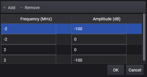
Opens the ![]() Filter Mask for Crest Factor Reduction editor to define a filter response in frequency domain. In the table, the frequency points must be entered with an order of increasing frequency in unit of MHz, and its corresponding amplitude is in unit of dB. When generating this filter mask, the frequency points between the specified points are linearly interpolated. When signal symbol rate is changed, this table will be automatically updated. User may need to adjust the mask manually to fit the signal bandwidth.
Filter Mask for Crest Factor Reduction editor to define a filter response in frequency domain. In the table, the frequency points must be entered with an order of increasing frequency in unit of MHz, and its corresponding amplitude is in unit of dB. When generating this filter mask, the frequency points between the specified points are linearly interpolated. When signal symbol rate is changed, this table will be automatically updated. User may need to adjust the mask manually to fit the signal bandwidth.
The format of Filter Mask string, appearing in the parameter field, is: <freq 1>,<amp 1>; <freq 2>,<amp 2>;….<freq n>,<amp n>.
|
SCPI Command |
[:SOURce]:RADio:CMODulation:WAVeform:CFReduction:FMASk [:SOURce]:RADio:CMODulation:WAVeform:CFReduction:FMASk? |
|
SCPI Example |
|
|
Couplings |
Each filter setup is composed by frequency (MHz) and amplitude (dB) with "," as separator. ";" is used to separate every filter. |
|
Preset |
" -2,-100;-2,0;2,0;2,-100" |
|
State Saved |
Yes |
|
Initial S/W Revision |
A.14.00 |
Enable or disable the multicarrier mode for waveform generation, when enabled, waveform which has at least one carrier will be generated, the count of carriers is decided by the frequency offsets definition, When disabled, waveform with only one carrier will be generated.
|
SCPI Command |
[:SOURce]:RADio:CMODulation:WAVeform[:ARB]:MCARrier[:STATe] ON|OFF|1|0 [:SOURce]:RADio:CMODulation:WAVeform[:ARB]:MCARrier[:STATe]? |
|
SCPI Example |
|
|
Couplings |
|
| Choices | On | Off |
|
Preset |
Off |
|
State Saved |
Yes |
|
Initial S/W Revision |
A.14.00 |
Indicate how many carriers has been defined and is a read only value.
|
SCPI Command |
[:SOURce]:RADio:CMODulation:WAVeform:CARRier:COUNt? |
|
SCPI Example |
|
|
Couplings |
This is a read only setting. The value is coupled with Frequency Offsets . The number is same with the number of values defined in Frequency Offsets Setting, please refer to Frequency Offsets for more information. |
|
Preset |
1 |
|
State Saved |
Yes |
|
Initial S/W Revision |
A.14.00 |
Define the initial phase of every carrier when multicarrier mode enabled. “Fixed” means all carriers has same initial phase which is zero; “Random” means initial phase of every carrier is random value.
|
SCPI Command |
[:SOURce]:RADio:CMODulation:WAVeform:MCARrier:PHASe FIX|RANDom [:SOURce]:RADio:CMODulation:WAVeform:MCARrier:PHASe? |
|
SCPI Example |
|
|
Couplings |
|
| Choices | Fixed | Random |
|
Preset |
RANDom |
|
State Saved |
Yes |
|
Initial S/W Revision |
A.14.00 |
Define the payload data offset between each carriers when multicarrier mode enabled, it is only applied for Custom IQ.
|
SCPI Command |
[:SOURce]:RADio:CMODulation:WAVeform:MCARrier:DATA:OFFSet <integer> [:SOURce]:RADio:CMODulation:WAVeform:MCARrier:DATA:OFFSet? |
|
SCPI Example |
|
|
Couplings |
|
|
State Saved |
Yes |
|
Minimum Value |
0 |
|
Maximum Value |
65535 |
|
Preset |
0 |
|
Initial S/W Revision |
A.14.00 |
Opens a window where you can define the frequency offset of every carrier for multicarrier mode. There are three methods that can be used:
To configure by individual carrier, use "," as delimiter. For example: "1MHz,2MHz,10MHz,20MHz" as frequency offsets for 4 carriers.
To configure by a range of carriers, use ":" to define the start frequency offset of first carrier, frequency step and the count of multi carriers. For example,"1MHz:2MHz:5" means 5 carriers offsets defined as "1MHz,3MHz,5MHz, 7MHz,9MHz"
Above 2 ways can be used by combination. For example: "1MHz:2MHz:5, 20MHz,30MHz"
Each frequency value can be used with unit (K, KHZ, M, MHZ, G, GHZ, HZ). When the value is without unit, the default unit HZ will be used. For example, you can input it as "2K, 4MHz" or "2, 4" . And the unit is case insensitive.
|
SCPI Command |
[:SOURce]:RADio:CMODulation:WAVeform:MCARrier:FREQuency:OFFSet [:SOURce]:RADio:CMODulation:WAVeform:MCARrier:FREQuency:OFFSet? |
|
SCPI Example |
RADio:CMODulation:WAVeform:MCARrier:FREQuency:OFFSet "4M, 2K" |
|
Couplings |
|
|
Preset |
0Hz |
|
State Saved |
Yes |
|
Initial S/W Revision |
A.14.00 |
Opens a window where you can define the power offset of every carrier for multicarrier mode. There are three methods that can be used:
To configure by individual power offsets, use "," as delimiter. For example: "0,-1,0,-1" means the power offset for 1st carrier is 0 dB , -1dB for 2nd carrier, 0dB for 3rd carrier and -1dB for 4th carrier.
To configure by a range of power offsets, use ":" to define the power offset of first carrier, power offset step and the count of multi carriers. For example,"0:-1:5" means "0,-1,-2, -3,-4".
Above 2 ways can be used by combination. For example: "0:-1:5, -8,-9".
The count of final power offsets definition is also decided by value of frequency offsets, because they need to have the same count.
Unit is dB.
|
SCPI Command |
[:SOURce]:RADio:CMODulation:WAVeform:MCARrier:POWer:OFFSet [:SOURce]:RADio:CMODulation:WAVeform:MCARrier:POWer:OFFSet? |
|
SCPI Example |
|
|
Couplings |
|
|
Preset |
0 |
|
State Saved |
Yes |
|
Initial S/W Revision |
A.14.00 |
Coupling: Coupled with VSA Equalization Data File and Equalization Bandwidth.
Enable or disable equalization for waveform generation. When enabled, equalization will be applied to the generated waveform according to the EQ Data from VSA.
|
SCPI Command |
[:SOURce]:RADio:CMODulation:WAVeform:EQUalization[:STATe] ON|OFF|1|0 [:SOURce]:RADio:CMODulation:WAVeform:EQUalization[:STATe]? |
|
SCPI Example |
|
|
Couplings |
|
| Choices | On | Off |
|
Preset |
Off |
|
State Saved |
Yes |
|
Initial S/W Revision |
A.14.00 |
Choices: The file type should be .csv
Load the EQ data file from VSA. You can type the directory of the EQ file or browse it in your computer.
|
SCPI Command |
[:SOURce]:RADio:CMODulation:WAVeform:EQUalization:FILE [:SOURce]:RADio:CMODulation:WAVeform:EQUalization:FILE? |
|
SCPI Example |
|
|
Couplings |
|
|
Preset |
Load the EQ data file from VSA |
|
State Saved |
Yes |
|
Initial S/W Revision |
A.14.00 |
The equalization will be performed within this bandwidth.
|
SCPI Command |
[:SOURce]:RADio:CMODulation:WAVeform:EQUalization:BWIDth <real> [:SOURce]:RADio:CMODulation:WAVeform:EQUalization:BWIDth? |
|
SCPI Example |
|
|
Couplings |
Coupled with the sampling rate of the waveform |
|
Preset |
40000000 |
|
State Saved |
Yes |
|
Minimum Value |
0 |
|
Maximum Value |
Dynamic Max value. Equalization bandwidth should not be larger than the sampling rate of the waveform. |
|
Initial S/W Revision |
A.14.00 |
Group and Signal settings determine where the specific waveform of Custom Modulation is played. The waveform file name will have a _G#S# suffix based on the routing configuration. So, you can specify different Group/Signal to generate/playback/edit this waveform.
Assign the signal group number.
|
SCPI Command |
[:SOURce]:RADio:CMODulation:WAVeform:ROUTing:GROup <integer> [:SOURce]:RADio:CMODulation:WAVeform:ROUTing:GROup? |
|
SCPI Example |
|
|
Couplings |
|
|
Preset |
1 |
|
State Saved |
Yes |
|
Minimum Value |
1 |
|
Maximum Value |
8 |
|
Initial S/W Revision |
A.14.00 |
Assign the signal number.
|
SCPI Command |
[:SOURce]:RADio:CMODulation:WAVeform:ROUTing:SIGNal <integer> [:SOURce]:RADio:CMODulation:WAVeform:ROUTing:SIGNal? |
|
SCPI Example |
|
|
Couplings |
|
|
Preset |
1 |
|
State Saved |
Yes |
|
Minimum Value |
1 |
|
Maximum Value |
8 |
|
Initial S/W Revision |
A.14.00 |
The graph view displays several different representations of the generated waveform.
For more information, see Graph View.