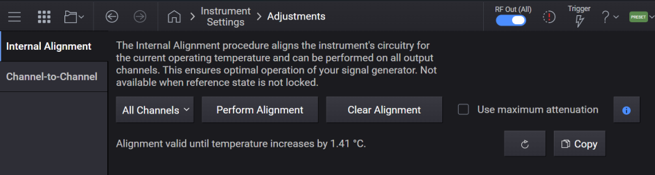
This screen accesses the alignment system of the instrument.
Run Individual Channel Alignment
Clear Individual Channel Alignment
Specify Device for RF Power Accuracy Adjustment
Clear Power Accuracy Adjustment
Runs the internal alignment for all channels in the instrument and stores the data, if successful. This ensures optimal operation of your signal generator. While alignment is running, no other operation of the instrument is allowed.
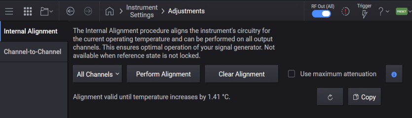
To maintain instrument accuracy, it is important to keep the instrument aligned. It is recommended to perform this alignment following the initial setup of the instrument, and periodically thereafter.
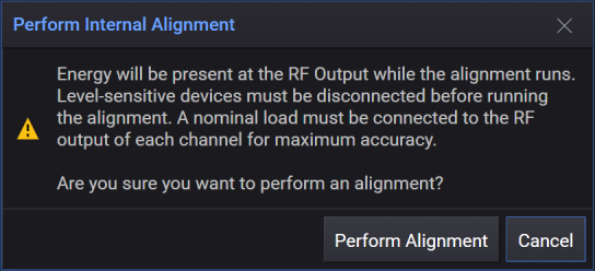
Energy will be present at the RF Output while alignment runs. Level-sensitive devices must be disconnected before running alignment.
The RF Output can be terminated with a 50-ohm load if you want to eliminate such signals from being broadcast in your test environment.
Runs the internal alignment for all channels in the instrument and stores the data if successful. While alignment is running, no other operation of the instrument is allowed.
Energy will be present at the RF Output while alignment runs. Level-sensitive devices must be disconnected before running alignment.
The RF Output can be terminated with a 50-ohm load if you want to eliminate such signals from being broadcast in your test environment.
|
GUI Location |
System Menu > Settings (gear icon) > Adjustments > Internal Alignment > Perform Alignment |
|
SCPI Command |
*CAL? |
|
SCPI Example |
*CAL? |
|
Notes |
Returns 0 if successful. Returns 1 if failed. While performing the alignment, the Calibrating bit (bit 0 in the Status Operation register) is set. Completion, or termination, will clear bit 0 in the Status Operation register. This command is sequential; it must complete before further SCPI commands are processed. Interrupting the alignment from remote is accomplished by invoking Device Clear followed by the :ABORt command. With M1749A connected, alignments will take significantly longer. If running alignments using SCPI, ensure your timeout is set to take this into account. Alignment will be needed after bootup whenever V3080A’s capabilities have been removed or added since the previous application run, as well as when the V3080A’s serial has changed between application runs. *CAL? is the same as doing a CAL:INT? for all channels. |
|
Initial S/W Revision |
A.01.00 |
Runs the internal alignment for an individual channel in the instrument and stores the data if successful.
|
GUI Location |
System Menu > Settings (gear icon) > Adjustments > Internal Alignment > All Channels > Channel <n> |
|
SCPI Command |
:CALibration<channel>:INTernal? |
|
SCPI Example |
:CAL:INT? ! Aligns channel 1 and returns a value :CAL2:INT? ! Aligns channel 2 and returns a value |
|
Notes |
The subopcode specifies the channel to align. Returns 0 if successful. Returns 1 if failed. While performing the alignment, the appropriate bit(s) in the STATus:OPERation:ALIGning and STATus:OPERation:ALIGning:EALigning registers are set. Completion, or termination, will clear the appropriate bit(s) in the STATus:OPERation:ALIGning and STATus:OPERation:ALIGning:EALigning registers. This command is sequential; it must complete before further SCPI commands are processed. Interrupting the alignment from remote is accomplished by invoking Device Clear followed by the :ABORt command. With M1749A connected, alignments will take significantly longer. If running alignments using SCPI, ensure your timeout is set to take this into account. |
|
Initial S/W Revision |
A.01.00 |
|
Modified S/W Revision |
A.11.50 - added access from the GUI and the per-channel status registers |
For M9484C, it erases internal alignment data stored in memory for all channels, returning the alignment data to what was in place at the time of manufacturing. Alignment must be run following this action to achieve optimal operation of your signal generator.
This does not clear the factory-generated calibration data stored within the instrument.
After the clearing is performed, the message "Internal Alignment cleared, performance will be degraded. Alignment is required." is posted.
|
GUI Location |
System Menu > Settings (gear icon) > Adjustments > Internal Alignment > Clear Alignment |
|
SCPI Command |
:CALibration:INTernal:CLEar:ALL |
|
SCPI Example |
CAL:INT:CLE:ALL |
|
Status Bits/OPC Dependencies |
Bit 7 in the Status Questionable Register will be set after the alignment is cleared |
|
Initial S/W Revision |
A.09.00 |
For M9484C, it erases internal alignment data stored in memory for the specified channel, returning the alignment data for the indicated channel to what was in place at the time of manufacturing. The alignment that has been cleared must be run again to achieve optimal operation of your signal generator.
This does not clear the factory-generated calibration data stored within the instrument.
|
GUI Location |
System Menu > Settings (gear icon) > Adjustments > Internal Alignment > channel selected in All Channels listbox > Clear Alignment |
|
SCPI Command |
:CALibration<channel>:INTernal:CLEar |
|
SCPI Example |
:CAL:INT:CLE |
|
Status Bits/OPC Dependencies |
Set the appropriate bit(s) in the STATus:QUEStionable:CALibration:ANEeded and STATus:QUEStionable:CALibration:ANEeded:EANeeded registers. |
|
Initial S/W Revision |
A.01.00 |
|
Modified S/W Revision |
A.09.00 – added SCPI for M9484C A.11.50 - added access from the GUI and the per-channel status registers |
Remote command only.
Enables logging for all channels during alignment. Logs files will be saved at:
E:\Keysight\CalTestLogs
|
SCPI Command |
:CALibration:INTernal:LOG ON|OFF|1|0 :CALibration:INTernal:LOG? |
|
SCPI Example |
CAL:INT:LOG ON CAL:INT:LOG? |
| Preset | ON |
|
State Saved |
No |
|
Initial S/W Revision |
A.18.00 |
For M9484C:
For maximum power accuracy, the alignment process varies the internal attenuators to obtain internal correction factors. As a result, energy is present on the RF Output port. If your test environment cannot tolerate such energy during alignment, you can configure the alignment to maintain maximum internal attenuation, thus minimal energy on the RF Output port. When the alignment is configured to run with maximum attenuation, the accuracy may be impacted by +/- 0.5 dB.
The configuration of alignment to run with maximum attenuation applies to all channels in instruments with greater than one channel.
|
SCPI Command |
CALibration:POWer:AMAXimum ON|OFF|1|0 CALibration:POWer:AMAXimum? |
|
SCPI Example |
CAL:POW:AMAX ON CAL:POW:AMAX? |
|
Notes |
|
| Preset | OFF |
|
State Saved |
No |
| Range | OFF | ON |
|
Initial S/W Revision |
A.15.00 |
Remote command only.
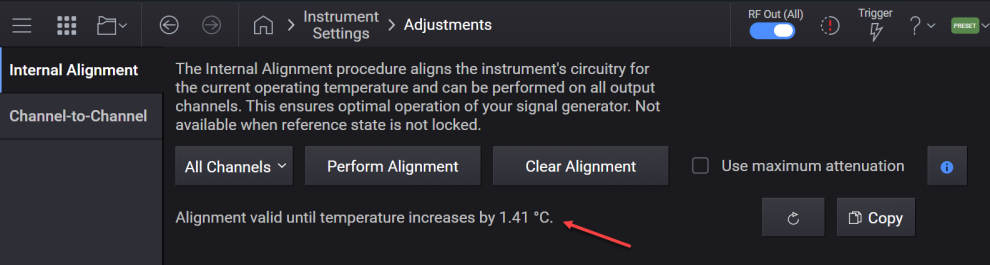
Query only. The instrument provides the amount of temperature change since the last successful alignment was performed. Performing a Clear Alignment clears the temperature at which the last successful alignment was performed.
|
SCPI Command |
CALibration:TEMPerature? |
|
SCPI Example |
CAL:TEMP? |
|
Notes |
The return is a list of two values: the first value is in degrees Celsius, and the second value is the channel number where the maximum delta exists. For example: CAL:TEMP? -1.2, 1 |
|
Initial S/W Revision |
A.14.00 |
| Modified at S/W Revision | A.18.01 - Changed to remote command only |
Query only. Returns the remaining temperature margin before an alignment is required. This value reflects how much the instrument’s temperature can drift before exceeding the threshold that necessitates a new alignment. Once the margin reaches zero , an alignment is required to calibrate the hardware. A negative value indicates how much the temperature has drifted beyond the threshold.
|
SCPI Command |
SYSTem:RF<Channel>:TEMPerature:AMARgin? |
|
SCPI Example |
SYST:RF1:TEMP:AMAR? |
|
Initial S/W Revision |
A.18.01 |
For M9484C with V3080A connected to one or more channels.
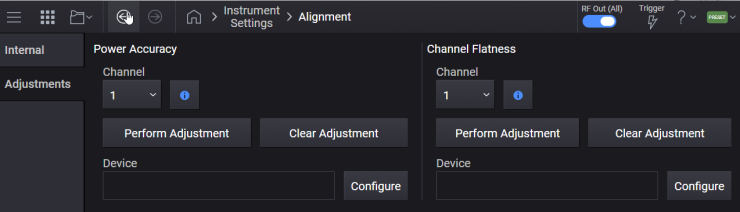
The Accuracy Adjustments calibrate the absolute amplitude accuracy of the RF output for the desired Channel. These Adjustments should be performed following the initial setup of the instrument, and any time after the cables are removed and reconnected.
Power Accuracy Adjustment: this compensates residual power offsets primarily due to system cabling. A Power Meter must be used for this adjustment.
Channel Flatness Adjustment: this corrects flatness across the modulation bandwidth. A Spectrum Analyzer must be used for this adjustment. The spectrum analyzer can be a Keysight Technologies N9041B with Option H1G or N9042B with at least 1 GHz bandwidth and V3050A. The spectrum analyzer must be calibrated with a Keysight Technologies U9361M RCal Receiver Calibrator.
|
GUI Location |
Settings (gear icon) >Alignment > Adjustments tab > Power Accuracy |
|
Initial S/W Revision |
A.012.00 |
For M9484C with V3080A connected.
Specifies a Power Meter from the Device List, for the RF Power Accuracy Adjustment on the specified channel.
To configure external devices in the Device List, go to the Device List.
|
GUI Location |
Settings (gear icon) > Alignment > Adjustments tab > Device for RF Power Accuracy Adjustment |
|
SCPI Command |
:CALibration<channel>:ACCuracy:POWer:DEVice <name> :CALibration<channel>:ACCuracy:POWer:DEVice? |
|
SCPI Example |
:CAL2:ACC:POW:DEV "myDevice" :CAL2:ACC:POW:DEV? |
|
Notes |
If the specified device does not exist in the Device List, an error will be raised: If the specified device is not a Power Meter device type, an error will be raised: |
|
Couplings |
If the device currently selected from the Device List is removed, this setting will default to "", the empty string. |
|
Initial S/W Revision |
A.12.00 |
For M9484C with V3080A connected.
Runs the Accuracy Adjustment on the specified channel.
Before invoking the RF Power Accuracy Adjustment, connect the power meter to the V3080A RF Output on the appropriate channel of the M9484C.
|
GUI Location |
Settings (gear icon) Alignment > Adjustments tab > Perform Adjustment |
|
SCPI Command |
:CALibration<channel>:ACCuracy:POWer |
|
SCPI Example |
CAL:ACC:POW |
|
Notes |
Before invoking the adjustment, ensure the power sensor is connected to the RF Output of the V3080A on the appropriate channel. If the adjustment is requested without a valid device selected, an error will be raised -220, "Parameter error; No device selected". The adjustment will take a significant amount of time. If running the adjustment using SCPI, ensure your timeout is set to take this into account. If the adjustment is requested on a model other than M9484C, or channel without V3080A connected, an error will be raised: |
|
Initial S/W Revision |
A.12.00 |
For M9484C with V3080A connected to one or more channels.
Clears the Power Accuracy Adjustment on the specified channel.
|
GUI Location |
Settings (gear icon) Alignment > Adjustments tab > Power Accuracy area > Clear |
|
SCPI Command |
:CALibration<channel>:ACCuracy:POWer:CLEar |
|
SCPI Example |
CAL:ACC:POW:CLE |
|
Notes |
If the adjustment is requested on a model other than M9484C, or channel without V3080A connected, an error will be raised: -200; "Execution error; adjustment requires a M9484C with a V3080A connected." |
|
Initial S/W Revision |
A.14.00 |
For M9484C with V3080A connected.
Specifies a Spectrum Analyzer from the Device List for the RF Channel Flatness Adjustment on the specified channel.
To configure external devices in the Device List, go to the Device List.
|
GUI Location |
Settings (gear icon) Alignment > Adjustments tab > Channel Flatness > Specify Device for Channel Flatness Adjustment |
|
SCPI Command |
:CALibration<channel>:ACCuracy:FLATness:DEVice <name> :CALibration<channel>:ACCuracy:FLATness:DEVice? |
|
SCPI Example |
:CAL2:ACC:FLAT:DEV "myDevice" |
|
Notes |
If the specified device does not exist in the Device List, an error will be raised: -220,"Parameter error; Specified device does not exist" |
|
Couplings |
If the device currently selected from the Device List is removed, this setting will default to "" – the empty string. |
|
Initial S/W Revision |
A.12.00 |
For M9484C with V3080A connected.
Clears the Channel Flatness Adjustment on the specified channel.
|
GUI Location |
Settings (gear icon) Alignment > Adjustments tab > Channel Flatness > Clear |
|
SCPI Command |
:CALibration<channel>:ACCuracy:FLATness:CLEar |
|
SCPI Example |
:CAL:ACC:FLAT:CLE |
|
Notes |
If the adjustment is requested on a model other than M9484C, or channel without V3080A connected, an error will be raised: -200; "Execution error; adjustment requires a M9484C with a V3080A connected." |
|
Initial S/W Revision |
A.14.00 |
For M9484C with V3080A connected.
Runs the RF Channel Flatness Adjustment on the specified channel.
The spectrum analyzer can be a Keysight Technologies N9041B with Option H1G or N9042B with at least 1 GHz bandwidth and V3050A. The spectrum analyzer must be calibrated with a Keysight Technologies U9361M RCal Receiver Calibrator. Follow this procedure before Run RF Channel Flatness Adjustment is invoked:
Connect the U9361M RCal to the 1.00 mm input on the spectrum analyzer using a same cable to be used when performing the RF Channel Flatness Adjustment of the M9484C.
Connect the U9361M RCal USB cable to the spectrum analyzer.
Connect the U9361M RCal 10 MHz Ext Ref In to the spectrum analyzer’s 10 MHz Ref Out.
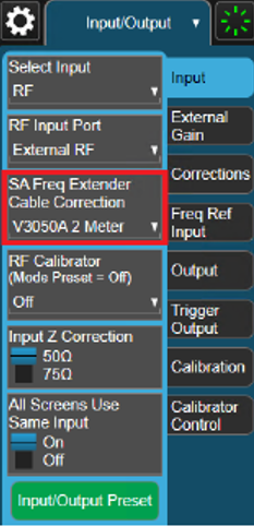
If using an N9042B with V3050A, ensure the same SA Freq Extended Cable correction is used when performing the RCal calibration as will be used when Run RF Channel Flatness Adjustment with M9484C.
On the spectrum analyzer, ensure the U9361M RCal device is identified.
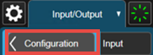
Select the Input/Output menu > Calibration tab > Configuration menu.
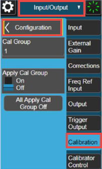
Select the Identify RCal Module button. The U9361M’s serial number will appear on the menu panel. If the U9361M RCal is not identified make the appropriate changes on the spectrum analyzer before proceeding. Ensure the spectrum analyzer contains the license for the U9361M, the USB communication is operating.
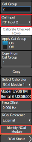
Select the appropriate Cal Input. For the N9041B it will be RF Input 2 and for the N9042B with V3050A it will be Ext RF. Select Configuration.
Enter the Cal Group number you will be using for the Run RF Channel Flatness Adjustment, recommendation is to use Cal Group 1.
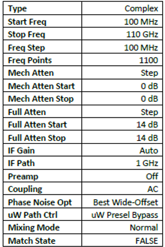
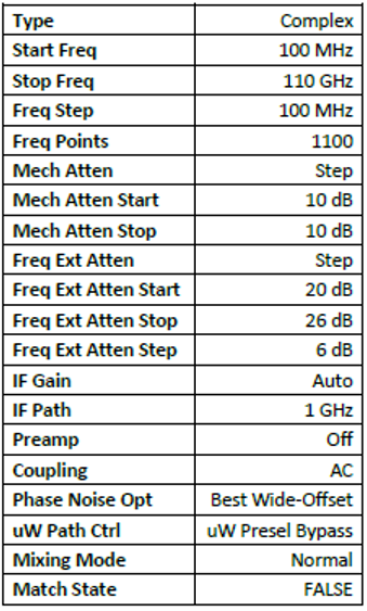
Input the properties for the calibration as follows, select Insert Row Below:
For N9041B:
For N9042B with V3050A:
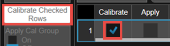
Select the row to Calibrate, then Calibrate Checked Rows:
Select OK when ready to invoke the calibration.
The procedure will take approximately 30 minutes to complete. When finished a timestamp will appear in the Last Calibrated table column.
Before invoking the RF Channel Flatness Adjustment connect the spectrum analyzer to the V3080A RF Output on the appropriate channel of the M9484C.
|
GUI Location |
Settings (gear icon) Alignment >Adjustments tab > Perform Adjustment |
|
SCPI Command |
:CALibration<channel>:ACCuracy:FLATness |
|
SCPI Example |
:CAL:ACC:FLAT |
|
Notes |
If the adjustment is requested without a valid device selected, an error will be raised -220, "Parameter error; No device selected". The adjustment will take a significant amount of time. If running the adjustment using SCPI, ensure your timeout is set to take this into account. If the adjustment is requested on a model other than M9484C, or channel without V3080A connected, an error will be raised: |
|
Initial S/W Revision |
A.12.00 |
Applies to M9484C only with license model N7653APPC.
For
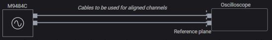
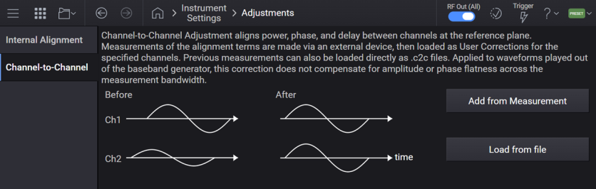
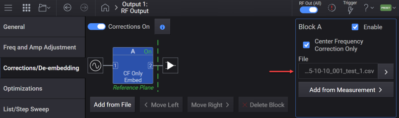
The Channel-to-Channel adjustment measurement results are then saved as .csv and .c2c files and loaded as corrections in Block A of the Corrections/De-embedding tab. The measured differences in phase, delay, and amplitude are then corrected in the signal source.
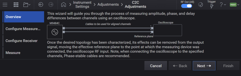
Allows you to configure and perform the channel-to-channel adjustment and load measurement results as corrections. The GUI provides a wizard to guide you through the steps.
Sets the start frequency for the Channel-to-Channel adjustment step array.
|
GUI Location |
Settings (gear icon) >Adjustments tab >Channel-to-Channel > Add From Measurement > Configure Measure...> Start Frequency |
|
SCPI Command |
CALibration:CTCHannel:STEP:STARt <freq> CALibration:CTCHannel:STEP:STARt? |
|
SCPI Example |
CAL:CTCH:STEP:STAR 1GHz CAL:CTCH:STEP:STAR? |
|
Coupling |
Coupled to Stop Frequency. If Start Frequency goes above Stop Frequency, Stop Frequency is automatically adjusted to Start Frequency. |
| Preset | 1 GHz |
| State Saved | Yes |
| Min | 9 kHz |
| Max |
For M9484C:
|
| Resolution | 10 µHz |
|
Initial S/W Revision |
A.18.01 |
Sets the stop frequency for the channel-to-channel adjustment step array.
|
GUI Location |
Settings (gear icon) >Adjustments tab >Channel-to-Channel > Add From Measurement > Configure Measure...> Stop Frequency |
|
SCPI Command |
CALibration:CTCHannel:STEP:STOP <freq> CALibration:CTCHannel:STEP:STOP? |
|
SCPI Example |
CAL:CTCH:STEP:STOP 1GHz CAL:CTCH:STEP:STOP? |
|
Coupling |
Coupled to Start Frequency. If Stop Frequency goes below Start Frequency, Start Frequency is automatically adjusted to Stop Frequency. |
| Preset | 6 GHz |
| State Saved | Yes |
| Min | 9 kHz |
| Max |
For M9484C:
|
| Resolution | 10 µHz |
|
Initial S/W Revision |
A.18.01 |
Sets the number of points in the channel-to-channel adjustment step array.
|
GUI Location |
Settings (gear icon) > Adjustments tab >Channel-to-Channel > Add From Measurement > Configure Measure...> Number of Points |
|
SCPI Command |
CALibration:CTCHannel:STEP:POINts <integer> CALibration:CTCHannel:STEP:POINts? |
|
SCPI Example |
CAL:CTCH:STEP:POIN 20 CAL:CTCH:STEP:POIN? |
| Preset | 6 |
| State Saved | Yes |
| Min | 2 |
| Max | 10000 |
|
Initial S/W Revision |
A.18.01 |
Sets the power level of the signal generated for the channel-to-channel adjustment measurement.
|
GUI Location |
Settings (gear icon) > Adjustments tab >Channel-to-Channel >Add From Measurement > Configure Measure... > Output Amplitude |
|
SCPI Command |
CALibration:CTCHannel:POWer:LEVel <ampl> CALibration:CTCHannel:POWer:LEVel? |
|
SCPI Example |
CAL:CTCH:POW:LEV -30dBm CAL:CTCH:POW:LEV? |
|
Preset |
-10 dBm |
| State Saved | Yes |
| Min | -135 dBm |
| Max | 0 dBm |
| Resolution | 0.01 dBm |
|
Initial S/W Revision |
A.18.01 |
Enables or disables aligning power levels with the channel-to-channel adjustment.
|
GUI Location |
Settings (gear icon) > Adjustments tab >Channel-to-Channel > Add From Measurement > Configure Measure...> Adjust |
|
SCPI Command |
CALibration:CTCHannel:POWer[:STATe] ON|OFF|0|1 CALibration:CTCHannel:POWer[:STATe]? |
|
SCPI Example |
CAL:CTCH:POW ON CAL:CTCH:POW? |
|
Preset |
ON |
| State Saved | Yes |
|
Initial S/W Revision |
A.18.01 |
Sets the tolerance (in degrees) within which phase should be used for the channel-to-channel adjustment. The adjustment algorithm will iterate up to three times to try and reach the tolerance values.
|
GUI Location |
Settings (gear icon) >Adjustments tab >Channel-to-Channel > Add From Measurement > Configure Measure... > Phase Tolerance |
|
SCPI Command |
CALibration:CTCHannel:PHASe:TOLerance <degrees> CALibration:CTCHannel:PHASe:TOLerance? |
|
SCPI Example |
CAL:CTCH:PHAS:TOL 1 deg CAL:CTCH:PHAS:TOL? |
|
Preset |
3 deg |
| State Saved | Yes |
| Min | 0 deg |
| Max | 90 deg |
| Resolution | 0.001 deg |
|
Initial S/W Revision |
A.18.01 |
Sets the tolerance within which delay should be used for the channel-to-channel adjustment. The adjustment algorithm will iterate up to three times to try and reach the tolerance values.
|
GUI Location |
Settings (gear icon) >Adjustments tab >Channel-to-Channel > Add From Measurement > Configure Measure...> Delay Tolerance |
|
SCPI Command |
CALibration:CTCHannel:DELay:TOLerance <time> CALibration:CTCHannel:DELay:TOLerance? |
|
SCPI Example |
CAL:CTCH:DEL:TOL 1 ns CAL:CTCH:DEL:TOL? |
|
Preset |
10 ps |
| State Saved | Yes |
| Min | 0 s |
| Max | 1 ns |
| Resolution | 1 fs |
|
Initial S/W Revision |
A.18.01 |
Sets the tolerance within which power should be used for the channel-to-channel adjustment. The adjustment algorithm will iterate up to three times to try and reach the tolerance values.
This setting is applicable when the Power State is set to ON.
|
GUI Location |
Settings (gear icon) >Adjustments tab >Channel-to-Channel > Add From Measurement > Configure Measure... > Amplitude Tolerance |
|
SCPI Command |
CALibration:CTCHannel:POWer:TOLerance <ampl> CALibration:CTCHannel:POWer:TOLerance? |
|
SCPI Example |
CAL:CTCH:POW:TOL 0.5 dB CAL:CTCH:POW:TOL? |
|
Preset |
0.1 dB |
| State Saved | Yes |
| Min | 0 |
| Max | 3 dB |
| Resolution | 0.001 dB |
|
Initial S/W Revision |
A.18.01 |
Channel-to-channel adjustment supports oscilloscopes with Keysight 89600 VSA software installed as measurement devices.
Specifies an Oscilloscope from the Device List. To configure external devices in the Device List, go to the Device List.
|
GUI Location |
Settings (gear icon) >Adjustments tab >Channel-to-Channel > Add From Measurement > Configure Receiver |
|
SCPI Command |
:SYSTem:COMMunicate:CTCHannel:DEVice <name> :SYSTem:COMMunicate:CTCHannel:DEVice? |
|
SCPI Example |
SYST:COMM:CTCH:DEV "myDevice" SYST:COMM:CTCH:DEV? |
| Preset | "" |
| State Saved | Yes |
|
Initial S/W Revision |
A.18.01 |
Runs the channel-to-channel adjustment measurement, with a compatible, connected oscilloscope.
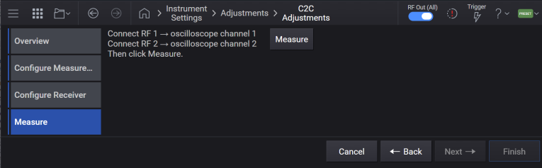
Upon successful completion, the resulting measurement data is saved to .csv and .c2c files in the Corrections directory, with the filename autogenerated based on the date/time. These correction files are then loaded in Block A of Corrections/De-embedding, and enabled on each of the channels specified for the adjustment.
The following features are disabled on each of the channels specified for the adjustment, as the adjustment cannot be guaranteed while using these features:
This command requires a base name for the output files and the channels to align as parameters. The resulting correction files will be stored in a directory created with the provided base name and will contain the correction files for each channel. Note that when a file path is provided, it can be either full or relative. When a relative path is provided, it will be based from the Corrections folder. For information on the correction file location, see File Location and Default Folders.
Example: The command CAL:CTCH:FILE:BNAME "myData",1,2 will result in a directory labeled "myData" containing myData_1.csv and myData_2.csv in the Corrections folder.
|
GUI Location |
Settings (gear icon) > Adjustments tab >Channel-to-Channel > Add From Measurement > Measure |
|
SCPI Command |
CALibration:CTCHannal:MEASure "<base name>",< channel>,... |
|
SCPI Example |
CAL:CTCH:MEAS "",1,2,3,4 |
| Notes |
The first argument must be an empty string. This field is reserved for future use. The channel list must contain a minimum of two channels, from channel 1 up to the maximum number of input channels on the oscilloscope. If one of the specified channels is not connected to the oscilloscope, an error message is generated. All channels in the list must be valid and distinct from one another. Relative corrections are applied in relationship to the lowest channel number provided. If aligning more channels than the available oscilloscope inputs, this command should be called several times, with the lowest channel number common to every invocation. For example, for aligning an 8 ports multi-instrument system using a 4-channel oscilloscope:
When Measure Correction Data is triggered, the process can be prematurely terminated and an error is generated, if any of the following conditions are met:
|
| Dependencies |
Available only when in Independent Configuration. This feature requires a Keysight oscilloscope with VSA installed and a license for vector measurement, with sufficient frequency range and bandwidth for signal analysis. Prior to running the adjustment:
|
| Couplings |
Upon successful completion of the adjustment, on all channels specified for adjustment:
|
| Min | 1 |
| Max | <channel count> |
| State Saved | No |
|
Initial S/W Revision |
A.18.01 |
GUI option only.
Reads the .c2c file containing correction data, loads each correction file into Block A of the corrections deembedding fixture, and enables it on each channel specified for adjustment.

Upon successful completion of loading corrections, the following actions are performed on all channels specified for adjustment:
The correction files are loaded into Block A Properties > File, replacing any file already loaded
Block A Properties - Enable is set to ON
Block A Properties "Absolute Power Corrections Only" is set to ON
Corrections Enable is set to ON
List/Step Sweep State is set to OFF
Use Harmonics Filters is set to OFF
Waveform sequencer is disabled