This capability requires Option CB4/CB5 and N7653APPC.
This topic comprises the following sections:
Instrument Nonlinear Correction Exclusions
Performing the Bonding Process
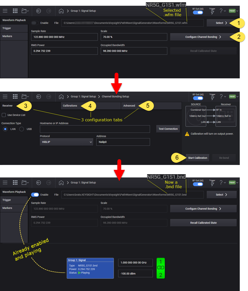
To play a high-fidelity bonded waveform it must first be configured and calibrated, using a ![]() process flow identical to Instrument Nonlinear Correction (INC).
process flow identical to Instrument Nonlinear Correction (INC).
From the System Menu, select Configure Channels > Channel Bonded > Apply. An interactive bonded block diagram appears.
For instruments with Option 8SG, only Signal 1 will be used while in bonded configuration.
Tap or click the Signal block and select a waveform file (*.wfm).
Tap or click Configure Channel Bonding to access the Channel Bonding Setup screen. Use the tabs to configure the receiver, calibrations, and advanced settings as appropriate for your testing use case. Refer to Performing the Bonding Process below.
Finally, tap or click Start Calibration. Upon completion of a successful calibration, a *.bnd file with the same name as the selected waveform file is created and vector modulation is enabled.
The bonding process supports the same set of calibrations as INC; however, an additional bonding calibration is always done by the bonding process. In some cases, the bonding calibration alone is sufficient to generate a high-fidelity bonded waveform. For these cases, the other calibrations should be disabled (unchecked in the GUI). This also results in a shorter calibration time.
The following capabilities of Instrument Nonlinear Correction do not apply in a bonded configuration:
Enable/Disable Instrument Nonlinear Correction
Applying a memory model
Recalling the Calibration State
The bonding process consists of: spectrally splitting a waveform into a set of sub-waveforms (one for each source-channel in the bonded group), aligning the source-channels, and improving the characteristics of each sub-waveform. The alignment process ensures the fidelity of the bonded signal where the frequencies generated by adjacent source-channels overlap. Certain instrument operations can affect the alignment of a bonded signal, without otherwise affecting the fidelity of the signal. In these cases, the most expedient fix is to perform a re-bonding only operation. Examples of situations where re-bonding may help are:
After re-starting the PathWave Signal Generator software,
After rebooting the M9484C,
After performing a Synchronization Alignment (M9484C),
After a period of time with significant temperature changes.
Once a *.bnd file is selected in a bonded configuration, a re-bonding can be performed. The following command will start the re-bonding process for the selected *.bnd file. This is not an overlapped operation and requires a combiner and receiver to be connected to the source. When re-bonding is done, only the power, phase and delay characteristics of the sub-waveforms and channels are affected.
For other cases, outlined below, the full bonding process should be repeated instead of performing a re-bonding:
After power, or frequency has been changed,
After the original unbonded waveform has changed (see Apply Bonded Correction),
Where changes to the Power, EVM, ACP, or Equalization calibrations are desired,
When re-bonding does not provide the desired improvements.
|
GUI Location |
Signals > Mode set to Waveform File, with a bonded (*.bnd) file loaded> Configure > Measure Correction > Re-bond |
|
SCPI Command |
[:SOURce]:GROup<group>:CBONded:REBond:RUN |
|
SCPI Example |
GRO:CBON:REB:RUN |
|
Couplings |
This will generate appropriate errors if the following conditions exist:
|
|
Notes |
GRO:CBON: REB:RUN can take a significant amount of time to complete depending on the waveform properties, and the receiver being used. Test software will need to set the timeout appropriately or handle timeout errors. |
|
Initial S/W Revision |
A.12.00 |
Although you perform this procedure in the Outputs 1 & 2 Channel Bonding Setup screen, each step links you to the description for the Instrument Nonlinear Calibration (INC) screen, as the user interface and SCPI commands are identical. Only the screen name is different. The steps below will also note information specific to channel bonding, as necessary.
Refer to Receiver Setup.
The settings under this tab enable you to configure and test connectivity to the receiver.
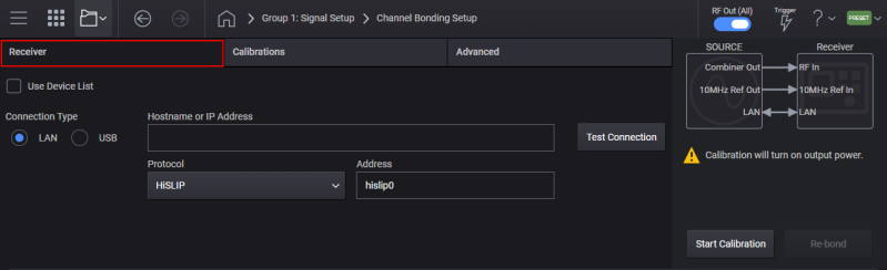
Refer to VISA Address of Receiver.
The SYS:COMM:REM:ADDR command is used to configure the receiver to use with the bonding process.
Refer to Start Calibration.
The GRO:SIGN:NCOR:INST:RUN command is used to start the bonding process.
Refer to Determining Calibration Completion Status.
The GRO:SIGN:NCOR:INST:RES? query is used to determine the completion status of the prior calibration.
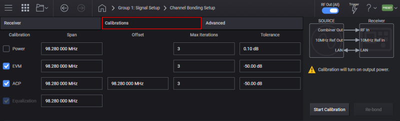
Refer to Calibrations Setup.
The bonding process not only bonds the set of physical channels, but can also perform the same calibrations on the resulting bonded waveform as the INC Calibration: Power, Distortion (EVM), Equalization, and ACP.
Refer to Power Calibration.
The GRO:SIGN:NCOR:INST:RES? query is used to determine the completion status of the prior calibration.
Refer to Power Calibration Tolerance.
The GRO:SIGN:NCOR:INST:POW:TOL command is used to specify the power calibration tolerance for the bonding process.
Refer to Power Calibration Maximum Iterations.
The GRO:SIGN:NCOR:INST:POW:ITER command is used to specify the maximum iterations of the power calibration tolerance for the bonding process.
Refer to Maximum Power for Power Calibration.
The GRO:SIGN:NCOR:INST:POW:PMAX command is used to specify the maximum power the source will utilize during the bonding process.
Refer to Cable Gain.
The GRO:SIGN:NCOR:INST:POW:CGA command is used to specify the cable gain for the bonding process.
Refer to Enable Distortion (EVM) Calibration.
The GRO:SIGN:NCOR:INST:DIST command is used to enable the distortion (EVM) calibration for the bonding process.
Refer to Distortion (EVM) Calibration Frequency Span.
The GRO:SIGN:NCOR:INST:DIST:SPAN command is used to specify the frequency bandwidth to use for the distortion (EVM) calibration during the bonding process.
Refer to Distortion (EVM) Calibration Maximum Iterations.
The GRO:SIGN:NCOR:INST:DIST:ITER command is used to specify the maximum number of iterations the distortion (EVM) calibration will perform during the bonding process.
Refer to Distortion (EVM) Calibration Tolerance.
The GRO:SIGN:NCOR:INST:DIST:TOL command is used to specify the tolerance for the distortion (EVM) calibration during the bonding process.
Refer to Enable Equalization Calibration.
This command is used to enable the equalization calibration during the bonding process.
An existing *.bnd file can be updated with new channel bonding data by:
Selecting an existing *.bnd file
Recall the calibrated state
Select only the Equalization calibration
Perform the calibration. The selected *.bnd file will be updated (and retain non-linear corrections from the prior calibration).
Refer to Enable ACP Calibration.
The GRO:SIGN:NCOR:INST:ACP command is used to enable the ACP calibration during the bonding process.
Refer to ACP Region Span / Bandwidth.
The GRO:SIGN:NCOR:INST:ACP:SPAN command is used to specify the bandwidth for the two ACP regions that the calibration will improve during the bonding process.
Refer to ACP Region Offset Frequency.
The GRO:SIGN:NCOR:INST:ACP:OFFS command is used to specify the center frequency offset for the two ACP regions that the calibration will improve during the bonding process.
Refer to ACP Maximum Iterations.
The GRO:SIGN:NCOR:INST:ACP:ITER command is used to specify the maximum iterations for the ACP calibration during the bonding process.
Refer to ACP Tolerance.
The GRO:SIGN:NCOR:INST:ACP:TOL command is used to specify the tolerance for the ACP calibration during the bonding process.
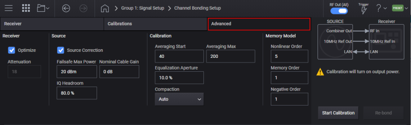
Refer to Advanced Setup.
This tab provides access to the following factory default calibration settings.
Refer to Receiver.
Refer to Receiver Optimization.
The GRO:SIGN:NCOR:INST:REC:OPT command is used to enable or disable receiver optimization for the bonding process.
Refer to Receiver Attenuator.
The GRO:SIGN:NCOR:INST:REC:ATT command is used for the bonding process.
Refer to Source.
Refer to IQ Headroom.
Refer to Source Correction.
Refer to Calibration.
Refer to Averaging Maximum for Distortion (EVM) Calibration.
Refer to Equalization Calibration Aperture.
Refer to Compaction.
Refer to Compaction Level.
Refer to Memory Model.
For Bonding, one memory model results for each channel in the bonded set of channels.
Refer to Nonlinear Order.
Refer to Memory Order.
Refer to Negative Order.
Refer to Data Extraction from INC or BND Files.
Using a Bonded Configuration (tutorial)
Bonded Configuration SCPI Example
Channel Bonding Temperature Compensation Using SCPI
Instrument Nonlinear Correction (INC) (user interface and SCPI descriptions)
Using Instrument Nonlinear Correction (INC) (tutorial)