FRC Configuration is based on TS 38 521-1 V17.4.1 (2022-07).
You can manually set three parameters via GUI or SCPI (see below) while others are Internally Set Parameters.
|
GUI Parameter |
Choices |
|---|---|
|
FRC Type |
FRC for receiver requirements for QPSK* FRC for maximum input level for 64QAM FRC for maximum input level for 256QAM |
|
Bandwidth |
FR1 10MHz* FR1 20MHz FR1 30MHz FR1 40MHz |
|
Subcarrier Spacing |
15 kHz* 30 kHz 60 kHz |
* default selection
|
SCPI Command |
[:SOURce]:RADio:NV2X:WAVeform[:ARB]:CCARrier<carrier>:CONFig:FRC " FRCType:QPSK|QAM64|QAM256, |
|
SCPI Example |
RAD:NV2X:WAV:CCAR0:CONF:FRC " FRCType: QAM64, Bandwidth: FR1BW20M, SubcarrierSpacing: SCS30K " |
|
Couplings |
Parameters and default values of FRC are list below: Bandwidth: FR1BW10M FRCType: QPSK SubcarrierSpacing: SCS15K One combined string is required to be input into the SCPI command. The format is "name: value , name: value …" . Default value will be used if parameter is not provided. The order of parameters does not matter. Parameter's name and value are case sensitive. |
The parameters described in the table below are set by the software.
|
Parameter |
Value |
Implementation |
|
|---|---|---|---|
|
BWP |
Allocated resource blocks |
Dynamic values |
RB Number |
|
PSCCH |
|
|
Enabled = true |
|
PSCCH resource |
10 PRBs, 3 symbols in time domain |
First Symbol = 1, Number of Symbols = 3 |
|
|
Slot number in 10ms |
10 ∗ 2µ µ = 0,1,2 for 15kHz, 30kHz, 60kHz |
Allocated Slots = 0:9, 0:19, 0:29, 0:39 |
|
|
PSSCH
|
|
|
Enabled = true |
|
Allocated resource blocks |
different value defined in spec |
RB Number |
|
|
sl-PSSCH-DMRSTimePatternList |
2 |
Number Of DMRS Symbols:2 |
|
|
CP-OFDM symbols per slot |
12 for all slots |
First Symbol = 1, last symbol = 12 |
|
|
Slot number in 10ms |
10 ∗ 2µ µ = 0,1,2 for 15kHz, 30kHz, 60kHz |
Allocated Slots = 0:9, 0:19, 0:29, 0:39 |
|
|
2nd stage SCI payload size |
35 |
SCI2 -> Payload Size = 35 |
|
|
Alpha value for SCI-2 |
1 |
SCI2 -> Scaling = 1.0 |
|
|
|
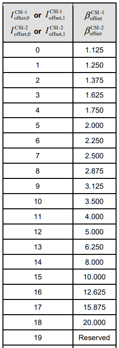
Beta offset for 2nd stage SCI |
different value defined in spec |
Beta Offset Index: value is taken from Table 9.3-2 below, which appears in TS 38 213 V16.10.0 9.3-2 |
Table 9.3-2: Mapping of beta_offset values for CSI and the index signaled by higher layers