WLAN
These waveform settings are applicable when you select 802.11ax as the PHY Specification.
Number of Data Symbols in One Frame
RF Burst Duration in One Frame
Overall Waveform Duration in One Frame
Configure MIMO with Mx1, Mx2, Mx4, and Mx8 in the HE SU PPDU Generation Mode.
When used to configure MIMO, the settings of AX will be internally reset to their default values. Then, the Number of Transmit Chains and the Number of Spatial Streams (Nss,u) will be set according to the user’s configuration." For example, if Mx2 is configured, Number of Transmit Chains and the Number of Spatial Streams (Nss,u) will be set to 2.
|
SCPI Command |
[:SOURce]:RADio:WLAN:WAVeform:AX:MIMO:CONFig NTX1| NTX2|NTX4|NTX8 |
|
SCPI Example |
RADio:WLAN:WAVeform:AX:MIMO:CONFig NTX8 |
|
Couplings |
|
|
Preset |
|
|
State Saved |
|
|
Initial S/W Revision |
A.17.00 |
Select the type of frame to be generated.
HE SU PPDU
HE Extended Range SU PPDU
HE MU PPDU
HE Trigger-Based PPDU
HE NDP
Non-HT
HE SU PPDU is a standard WLAN 802.11ax Single User PPDU format. It is constructed with legacy preamble, HE preamble and HE data portion and Packet Extension.
HE NDP format is the same as HE PPDU format without HE data portion.
Non-HT refers to the one defined by standard as Non-HT Duplicate Transmission, which is to repeat 802.11a signal in each 20 MHz segment.
|
SCPI Command |
[:SOURce]:RADio:WLAN:WAVeform:AX:GMODe SU|ERSU|MU|TB|NDP|NHT [:SOURce]:RADio:WLAN:WAVeform:AX:GMODe? |
|
SCPI Example |
|
|
Couplings |
|
|
Preset |
SU |
|
State Saved |
Yes |
|
Initial S/W Revision |
A.17.00 |
Select the bandwidth for IEEE 802.11ax. Please note that the instrument must have at least the equivalent bandwidth to allow the waveform to be successfully transmitted.
The HE extended Range SU PPDU is transmitted only on the primary 20 MHz.
|
SCPI Command |
[:SOURce]:RADio:WLAN:WAVeform:AX:BWIDth BW20M|BW40M|BW80M|BW160M|BW8080M [:SOURce]:RADio:WLAN:WAVeform:AX:BWIDth? |
|
SCPI Example |
|
|
Couplings |
|
|
Preset |
BW20M |
|
State Saved |
Yes |
|
Initial S/W Revision |
A.17.00 |
Enter an alpha-numeric comment of up to 32 characters. The comment resides in the file header and can include spaces and special characters.
|
SCPI Command |
[:SOURce]:RADio:WLAN:WAVeform:AX:COMMent [:SOURce]:RADio:WLAN:WAVeform:AX:COMMent? |
|
SCPI Example |
|
|
Couplings |
|
|
Preset |
|
|
State Saved |
Yes |
|
Initial S/W Revision |
A.17.00 |
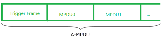
This parameter is selectable only when Generation Mode is set to HE SU PPDU, HE MU PPDU, or Non-HT. Otherwise it is read-only and set to Data and Control. When Frame Type is set to Trigger, the trigger frame (a MAC layer frame) structure varies according to the selected Generation Mode, as follows:
For HE SU PPDU, it solicits and allocates resources for UL MU transmissions. An SIFS after the PPDU carries the trigger frame. The trigger frame also carries other information required by the responding STA to send an HE trigger-based PPDU.
For HE MU PPDU, the transmitted data of each user is always an aggregated MPDU, which contains one trigger frame, and one or more MPDUs, as shown below.
For Non-HT, the PHY should be exactly the same as 802.11a/g if the bandwidth is 20 MHz. When a wider bandwidth is selected, the signal is just a duplication of multiple 20-MHz channels.
|
SCPI Command |
[:SOURce]:RADio:WLAN:WAVeform:AX:FRAMe:TYPE DATA|TRIGger [:SOURce]:RADio:WLAN:WAVeform:AX:FRAMe:TYPE? |
|
SCPI Example |
|
|
Couplings |
|
|
Preset |
DATA |
|
State Saved |
Yes |
|
Initial S/W Revision |
A.17.00 |
Use this cell to set the length (in microseconds) of the idle time after active PPDU frames. This is relevant only in framed mode.
No signal is transmitted during the idle interval, but the MAC layer operates as if a signal is being transmitted.
|
SCPI Command |
[:SOURce]:RADio:WLAN:WAVeform:AX:IDLE:INTerval <real> [:SOURce]:RADio:WLAN:WAVeform:AX:IDLE:INTerval? |
|
SCPI Example |
|
|
Couplings |
|
|
Preset |
2e-05 |
|
State Saved |
Yes |
|
Min |
0 |
|
Max |
|
|
Initial S/W Revision |
A.17.00 |
Set the idle interval ahead of frames in unit of seconds.
|
SCPI Command |
[:SOURce]:RADio:WLAN:WAVeform:AX:HEAD:IDLE:INTerval <real> [:SOURce]:RADio:WLAN:WAVeform:AX:HEAD:IDLE:INTerval? |
|
SCPI Example |
|
|
Couplings |
|
|
Preset |
0 |
|
State Saved |
Yes |
|
Min |
0 |
|
Max |
|
|
Initial S/W Revision |
A.17.00 |
Choose whether to use combined or separate waveforms for the two 80-MHz frequency segments.
Coupled with the number of instruments and the selected Bandwidth.
|
SCPI Command |
[:SOURce]:RADio:WLAN:WAVeform:AX:COMBined[:STATe] ON|OFF|1|0 [:SOURce]:RADio:WLAN:WAVeform:AX:COMBined[:STATe]? |
|
SCPI Example |
|
|
Couplings |
Visible only when you select 80+80 MHz as the Bandwidth. |
|
Preset |
OFF |
|
State Saved |
Yes |
|
Initial S/W Revision |
A.17.00 |
Sets the frequency spacing between two segments of 80+80 for the combined waveform. Its value is limited to an integer multiple of the subcarrier spacing to suppress ICI.
|
SCPI Command |
[:SOURce]:RADio:WLAN:WAVeform:AX:COMBined:FSPacing <real> [:SOURce]:RADio:WLAN:WAVeform:AX:COMBined:FSPacing? |
|
SCPI Example |
|
|
Couplings |
Visible only when Combined Waveform is set to ON. |
|
Preset |
0 |
|
State Saved |
Yes |
|
Min |
|
|
Max |
|
|
Initial S/W Revision |
A.17.00 |
Sets the number of frames.
|
SCPI Command |
[:SOURce]:RADio:WLAN:WAVeform:AX:FRAMe:COUNt <integer> [:SOURce]:RADio:WLAN:WAVeform:AX:FRAMe:COUNt? |
|
SCPI Example |
|
|
Couplings |
|
|
Preset |
1 |
|
State Saved |
Yes |
|
Min |
1 |
|
Max |
2000 |
|
Initial S/W Revision |
A.17.00 |
This is information indicating the generated waveform length in terms of sampling points.
|
SCPI Command |
[:SOURce]:RADio:WLAN:WAVeform:AX:SAMPles:COUNt? |
|
SCPI Example |
|
|
Couplings |
|
|
Preset |
4160 |
|
State Saved |
Yes |
|
Min |
|
|
Max |
|
|
Initial S/W Revision |
A.17.00 |
Number of OFDM Symbols in the Data portion of one frame.
|
SCPI Command |
[:SOURce]:RADio:WLAN:WAVeform:AX:FRAMe:DSYMbols? |
|
SCPI Example |
|
|
Couplings |
|
|
Preset |
2 |
|
State Saved |
Yes |
|
Min |
|
|
Max |
|
|
Initial S/W Revision |
A.17.00 |
The time duration of RF burst in one frame in unit of seconds.
|
SCPI Command |
[:SOURce]:RADio:WLAN:WAVeform:AX:FRAMe:BURSt:LENGth? |
|
SCPI Example |
|
|
Couplings |
|
|
Preset |
8.4e-05 |
|
State Saved |
Yes |
|
Min |
|
|
Max |
|
|
Initial S/W Revision |
A.17.00 |
The time duration of the overall waveform in one frame in unit of seconds.
|
SCPI Command |
[:SOURce]:RADio:WLAN:WAVeform:AX:FRAMe:LENGth? |
|
SCPI Example |
|
|
Couplings |
|
|
Preset |
1.04e-04 |
|
State Saved |
Yes |
|
Min |
0 |
|
Max |
|
|
Initial S/W Revision |
A.17.00 |
Use this cell to specify the number of times that the baseband signal is oversampled.
A higher oversampling ratio would help simplify the design of transmitting filter, but would result in a longer waveform.
|
SCPI Command |
[:SOURce]:RADio:WLAN:WAVeform:AX:OSRatio <real> [:SOURce]:RADio:WLAN:WAVeform:AX:OSRatio? |
|
SCPI Example |
|
|
Couplings |
|
|
Preset |
2 |
|
State Saved |
Yes |
|
Min |
|
|
Max |
|
|
Initial S/W Revision |
A.17.00 |
Reverse the spectrum of the waveform. This is useful for systems with external up conversion where the signal spectrum is mirrored by the up conversion process.
On: The Q channel is inverted, resulting in a mirrored spectrum.
Off: The spectrum is not inverted.
|
SCPI Command |
[:SOURce]:RADio:WLAN:WAVeform:AX:MIRRor:SPECtrum[:STATe] ON|OFF|1|0 [:SOURce]:RADio:WLAN:WAVeform:AX:MIRRor:SPECtrum[:STATe]? |
|
SCPI Example |
|
|
Couplings |
|
|
Preset |
OFF |
|
State Saved |
Yes |
|
Initial S/W Revision |
A.17.00 |
Set the duration of the transition time (Ttr) in the windowing function. Ttr creates a small overlap between consecutive subsections in order to smooth the transitions between them. Smoothing the transition is required in order to reduce the spectral sidelobes of the transmitted waveform.
Entering 0 samples means no windowing will be applied. A raised cosine time domain window is applied to the baseband signal to reduce out-of-band power.
|
SCPI Command |
[:SOURce]:RADio:WLAN:WAVeform:AX:WINDow:LENGth <integer> [:SOURce]:RADio:WLAN:WAVeform:AX:WINDow:LENGth? |
|
SCPI Example |
|
|
Couplings |
|
|
Preset |
2 |
|
State Saved |
Yes |
|
Min |
|
|
Max |
|
|
Initial S/W Revision |
A.17.00 |
A baseband filter is applied to reduce the transmitted bandwidth, increasing spectral efficiency.
For signals generated with digital signal processing, baseband filters are often finite impulse response (FIR) filters with coefficients that represent the sampled impulse response of the desired filter. FIR filters are used to limit the bandwidth of the input to the I and Q modulators.
Five options for baseband filtering can be selected in the Filter Type menu:
None: No filter.
Gaussian: The Gaussian filter does not have zero Inter-Symbol Interference (ISI). Wireless system architects must decide just how much of the ISI can be tolerated in a system and combine that with noise and interference. The Gaussian filter is Gaussian shaped in both the time and frequency domains, and it does not ring like the root cosine filters do. The effects of this filter in the time domain are relatively short and each symbol interacts significantly (or causes ISI) with only the preceding and succeeding symbols. This reduces the tendency for particular sequences of symbols to interact, which makes amplifiers easier to build and more efficient.
Root Raised Cosine: Root raised cosine, also referred to as square root raised cosine, filters have the property that their impulse response rings at the symbol rate. Adjacent symbols do not interfere with each other at the symbol times because the response equals zero at all symbol times except the center (desired) one. Root cosine filters heavily filter the signal without blurring the symbols together at the symbol times. This is important for transmitting information without errors caused by ISI. Note that ISI does not exist at all times, only at the symbol (decision) times.
You can change the values of the Root Raised Cosine Filter to optimize for better spectral characteristics (sharper roll-off on the band edges resulting in less adjacent channel power) vs. better EVM.
However, to reduce the value of Alpha will make the roll-off sharper but cause worse EVM.
Ideal Lowpass: In the frequency domain, this filter appears as a low-pass, rectangular filter with very steep cut-off characteristics. The pass band is set to equal the symbol rate of the signal. Due to a finite number of coefficients, the filter has a predefined length and is not truly "ideal." The resulting ripple in the cut-off band is effectively minimized with a Hamming window. This filter is recommended for achieving optimal ACP. A symbol length of 32 or greater is recommended for this filter.
User Defined: Allows you to select a simple unformatted text file (*.txt) of coefficient values, characterizing a user-defined filter. Each line in the file contains one coefficient value. The number of coefficients listed must be a multiple of the selected oversampling ratio. Each coefficient applies to both I and Q components.
|
SCPI Command |
[:SOURce]:RADio:WLAN:WAVeform:AX:FILTer:TYPE NONE|GAUSsian|RRCosine|LPASs|UDEFined [:SOURce]:RADio:WLAN:WAVeform:AX:FILTer:TYPE? |
|
SCPI Example |
|
|
Couplings |
|
|
Preset |
NONE |
|
State Saved |
Yes |
|
Initial S/W Revision |
A.17.00 |
This cell sets the filter's bandwidth-time product (BT) coefficient. It is valid only for a Gaussian filter.
B is the 3 dB bandwidth of the filter and T is the duration of the symbol period. BT determines the extent of the filtering of the signal. Occupied bandwidth cannot be stated in terms of BT because a Gaussian filter's frequency response does not go to zero, as does a root cosine filter. Common values for BT are 0.3 to 0.5. As the BT product is decreased, the ISI increases.
|
SCPI Command |
[:SOURce]:RADio:WLAN:WAVeform:AX:FILTer:BT <real> [:SOURce]:RADio:WLAN:WAVeform:AX:FILTer:BT? |
|
SCPI Example |
|
|
Couplings |
Only shown when FilterType is Gaussian. |
|
Preset |
0.5 |
|
State Saved |
Yes |
|
Min |
|
|
Max |
|
|
Initial S/W Revision |
A.17.00 |
This cell sets the filter's alpha coefficient. It is valid only for root cosine filters.
The sharpness of a root cosine filter is described by the filter coefficient, which is called alpha. Alpha gives a direct measure of the occupied bandwidth of the system and is calculated as: occupied bandwidth = symbol rate X (1 + alpha). If the filter had a perfect (brick wall) characteristic with sharp transitions and an alpha of zero, the occupied bandwidth would be: symbol rate X (1 + 0) = symbol rate. An alpha of zero is impossible to implement. Alpha is sometimes called the "excess bandwidth factor" as it indicates the amount of occupied bandwidth that will be required in excess of the ideal occupied bandwidth (which would be the same as the symbol rate).
At the other extreme, take a broader filter with an alpha of one, which is easier to implement. The occupied bandwidth for alpha = 1 will be: occupied bandwidth = symbol rate X (1 + 1) = 2 X symbol rate. An alpha of one uses twice as much bandwidth as an alpha of zero. In practice, it is possible to implement an alpha below 0.2 and make good, compact, practical radios. Typical values range from 0.35 to 0.5, though some video systems use an alpha as low as 0.11.
|
SCPI Command |
[:SOURce]:RADio:WLAN:WAVeform:AX:FILTer:ALPHa <real> [:SOURce]:RADio:WLAN:WAVeform:AX:FILTer:ALPHa? |
|
SCPI Example |
|
|
Couplings |
Only shown when FilterType is RootRaisedCosine. |
|
Preset |
0.5 |
|
State Saved |
Yes |
|
Min |
|
|
Max |
|
|
Initial S/W Revision |
A.17.00 |
This cell sets the effective bandwidth for the ideal low pass filter. It is valid only for low pass filters.
|
SCPI Command |
[:SOURce]:RADio:WLAN:WAVeform:AX:FILTer:BW <real> [:SOURce]:RADio:WLAN:WAVeform:AX:FILTer:BW? |
|
SCPI Example |
|
|
Couplings |
Only shown when FilterType is IdealLowpass. |
|
Preset |
20 |
|
State Saved |
Yes |
|
Min |
|
|
Max |
|
|
Initial S/W Revision |
A.17.00 |
The symbol length of the filter determines how many symbol periods will be used in the calculation of the symbol. The filter selection influences the symbol length value.
The Gaussian filter has a rapidly decaying impulse response. A symbol length of 6 is recommended. Greater lengths have negligible effects on the accuracy of the signal.
The root cosine filter has a slowly decaying impulse response. It is recommended that a long symbol length, around 32, be used. Beyond this, the ringing has negligible effects on the accuracy of the signal.
The ideal low pass filter also has a very slow decaying impulse response. It is recommended that a long symbol length, 32 or greater, be used.
For both root cosine and ideal low pass filters, the greater the symbol length, the greater the accuracy of the signal. Try changing the symbol length, and plotting the spectrum to view the effect the symbol length of the filter has on the spectrum.
|
SCPI Command |
[:SOURce]:RADio:WLAN:WAVeform:AX:FILTer:LENGth <integer> [:SOURce]:RADio:WLAN:WAVeform:AX:FILTer:LENGth? |
|
SCPI Example |
|
|
Couplings |
Only shown when FilterType is Gaussian, RootRaisedCosine, or IdealLowpass.
|
|
Preset |
6 |
|
State Saved |
Yes |
|
Min |
|
|
Max |
|
|
Initial S/W Revision |
A.17.00 |
This is valid only for user-defined filters.
When you select User Defined as the Filter Type, click the > button displayed with this field to select a simple unformatted text file (*.txt) of coefficient values, characterizing a user-defined filter. Each line in the file contains one coefficient value. The number of coefficients listed must be a multiple of the selected oversampling ratio. Each coefficient applies to both I and Q components.
|
SCPI Command |
[:SOURce]:RADio:WLAN:WAVeform:AX:FILTer:FILTer:COEFficient [:SOURce]:RADio:WLAN:WAVeform:AX:FILTer:FILTer:COEFficient? |
|
SCPI Example |
|
|
Couplings |
Only shown when FilterType is UserDefined.
|
|
Preset |
1 |
|
State Saved |
Yes |
|
Initial S/W Revision |
A.17.00 |
This setting is read only and displays the source for Marker 1.
The default is Frame Start that indicates the beginning of each frame. It starts at the beginning of the Head Idle Interval.
|
SCPI Command |
[:SOURce]:RADio:WLAN:WAVeform:AX:M1Source? |
|
SCPI Example |
|
|
Couplings |
|
|
Preset |
FSTart |
|
State Saved |
Yes |
|
Initial S/W Revision |
A.17.00 |
This setting is read only and displays the source for Marker 2.
The default is RF Blanking. It controls On/Off of the RF signal. There is a 500 ns pre-blanking before the Preamble part and a 335 ns latency after the Data part for Marker2.
|
SCPI Command |
[:SOURce]:RADio:WLAN:WAVeform:AX:M2Source? |
|
SCPI Example |
|
|
Couplings |
|
|
Preset |
BLANking |
|
State Saved |
Yes |
|
Initial S/W Revision |
A.17.00 |
This setting is read only and displays the source for Marker 3.
The default is Frames. It indicates the period of each frame. The Head Idle Interval is included in the frame, and the Idle Interval is excluded.
|
SCPI Command |
[:SOURce]:RADio:WLAN:WAVeform:AX:M3Source? |
|
SCPI Example |
|
|
Couplings |
|
|
Preset |
FRAMes |
|
State Saved |
Yes |
|
Initial S/W Revision |
A.17.00 |
This setting is read only and displays the source for Marker 4.
The default is Preamble Blanking. It indicates the Preamble part of each frame.
|
SCPI Command |
[:SOURce]:RADio:WLAN:WAVeform:AX:M4Source? |
|
SCPI Example |
|
|
Couplings |
|
|
Preset |
PREamble |
|
State Saved |
Yes |
|
Initial S/W Revision |
A.17.00 |