Agilent 8960 Fading Measurement Example
The following measurement example performs a DPCH block error rate (BLER) test on a W-CDMA UE (i.e. DUTor MS) using an Agilent E5515C/8960 wireless communications test set with the E6785 Fast Switching Lab Application (ver. G.00.15 or later), and an Agilent N5106A PXB baseband generator and channel emulator.
8960 requirements:
PXB requirements:
- at least one baseband card
- N5106A-8FP - Connect to E5515C (8960)
- N5106A-QFP - Fading with SISO Channel Models
- N5106A-JFP - Calibrated AWGN (optional/recommended)
* PXB firmware version 1.5.3 supports only the E6703 lab application. 8960 DC-HSPA support requires PXB firmware version 2.0.0 or later.
1. Configure the Hardware
 Detailed Steps
-
Connect PXB external reference output to the 8960 10 MHz reference input.
-
Connect a USB to GPIB converter from the PXB USB port to the 8960 GPIB port.
-
Connect an LVDS cable from the PXB digital bus port to the 8960’s digital bus port.
Note: The PXB digital bus port is also the logical port assignment that you will need to select when you add the 8960 to the PXB’s list of external instruments. A1 is the default PXB digital bus port, and it is the upper-left port looking at the back of the PXB.
-
Connect a W-CDMA test phone (UE) to the 8960 RF IN/OUT port.
Note: It’s also helpful to have a DC adapter for the phone so you don’t run out of battery.
2. Set Up the 8960
Detailed Steps
-
Turn on the 8960. Press the SYSTEM CONFIG key immediately after powering on to select an application.
-
If running the E6785 fast switch lab application, switch to the WCDMA format (SYSTEM CONFIG > F2/Format Switch > WCDMA).
-
Set the cell power to -50 dBm (CALL SETUP > F7/Cell Power).
-
Set the channel type to 64k RMC (CALL SETUP > F8/Channel Type).
-
Set the UE Loopback to “Type 2” (CALL SETUP > Call Control 3 of 6 > F6/RB Test Mode Setup > UE Loopback Type).
-
Set the Uplink DTCH RMC CRC Presence to “Used for Data” (CALL SETUP > Call Control 3 of 6 > F6/RB Test Mode Setup > Uplink DTCH RMC CRC Presence).
-
Don’t originate call yet.
Note: The fader must be enabled and in “Pass Through” mode before setting up a call. Otherwise, the call will be dropped as the connection to the PXB is established.
3. Set Up the PXB
Detailed Steps
-
Turn on the PXB.
-
Add 8960 to external instrument table.
-
In the configuration browser, under the Fade (ext in) node, select 1 Channel.
-
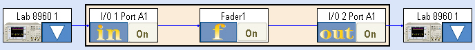
Set up the instrument configuration in the block diagram. Click on the triangle in the first block and select the 8960 that you just set up in the external instrument table. Assign this instrument to IO Port A1. Then click the Load Configuration button.
-
Select W-CDMA/Mobile Station/Case 1 fading profile
-
Set up AWGN
- Signal To Noise Ratio = 9.00 dB
- Output MUX = Signal Only
-
AWGN Enabled = ON
-
Fader Block = Pass Through (Thr)
-
If the PXB is in Manual calibration mode, you will need to press the Calibrate Power button before pressing Play.
-
Press the Play button
Note: Now the signal is running thru the fader, but is unimpaired (i.e. just pass thru). Now it is ok to setup a call. And then the fading and AWGN impairments can be added.
4. Verify Basic Unimpaired Operation
Detailed Steps
-
On 8960, originate call to verify that the UE connects and signal travels through PXB in Pass-Through mode.
Note: If you are having problems establishing a connection to the phone, make sure the PXB fader block is in Pass-Through (“Thr”) mode, and the PXB AWGN Output MUX is set to Signal Only.
5. Perform DPCH block error rate (BLER) tests
Repeat the following steps to verify the Block Error Ratio for each DPCH power level value listed in the 3GPP TS 34.121-1 v8.6.0 specification.
Detailed Steps
-
Set Cell 1 Connected DPCH Level to -13.9 dB (CALL SETUP > Call Control 2 of 6 > F3/Generator Info > F3/Downlink Channel Levels > F3/Connected DL Channel Levels > F2/WCDMA Conn DL Channel Levels > Cell 1 Connected DPCH Level).
-
Open the Block Error Ratio Measurement.
-
Open Block Error Setup to set the desired number of blocks. In this example we will use 2000 blocks (the specification calls for 8200 blocks for statistical accuracy, but use a lower number for demonstration purposes to avoid long wait times).
-
On PXB:
-
Reset the Measurement so it starts again.
-
Observe the block count. You should see the count slowly update in increments of 500 blocks (this will take quite a few seconds). When finished, the 8960 will display the Block Error Ratio results.
-
Repeat Step 5 using the next DPCH power level in the specification.