
A transmitted
signal undergoes changes while traveling through the propagation path
to the receiver. The effect of these changes is commonly called fading.
In free-space, a signal follows one path and arrives at the receiver with
little attenuation. This is not the case for a signal that encounters
obstacles in the propagation path. Instead, the signal is reflected, diffracted,
and scattered from objects that are present in the path. Each path can
have a different amount of attenuation, delay, and fading type. The combination
of these different paths is termed
At the receiver, the signals can add constructively or destructively, causing random and rapid fluctuations in the received amplitude when the receiver or the transmitter is moving. Due to the Doppler effect, this situation also causes the signal to be spread in the frequency domain.
The fading phenomena can be classified into two main groups known as large scale fading and small scale fading. The large scale fading is used to describe the signal level at the receiver after traveling over a large area (hundreds of wavelengths). Small scale fading is used to describe the signal level at the receiver after encountering obstacles near (several wavelengths to fractions of wavelengths) the receiver.
Large-scale fading is the result of signal attenuation due to signal propagation over large distances and diffraction around large objects in the propagation path.
Relative Path Loss (loss due to distance)
In free-space,
the attenuation of a signal due to distance follows the 1/d2
law, where
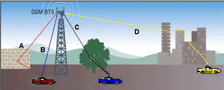
Log normal shadowing is the result of the signal being blocked by large objects in the propagation path (path D). These are typically distant objects in the environment such as mountains, hills, or large buildings. The length of time it takes for a moving receiver to pass through the "shadow" of these obstacles brings about the term "slow fading". The statistical model used to describe shadowing is the log-normal distribution of the mean signal power.
Rayleigh
fading is used to simulate the rapid amplitude fluctuations where there
is no direct ray component. Because there is no direct ray component,
Rayleigh fading is often classified as the worst case fading type. Using
a one ray model, this small scale distribution simulates the effects of
rapid amplitude fluctuations when the receiver travels a distance of a
few wavelengths. The one ray is scattered near the receiver resulting
in
a large number of rays arriving at the receiver from all directions
(path

The
Suzuki fading superimposes the log normal distribution onto the Rayleigh distribution. This is often used to simulate the effects of a dense urban environment with the average received power level fluctuating slowly due to shadowing effects. The log normal distribution is defined by the standard deviation of the average signal power level and a decorrelation length, which determines the rate at which the average power level changes. The decorrelation length determines the size of the shadow the receiver is moving through. The decorrelation length along with the vehicle speed determines the actual rate at which the average signal power level changes at the receiver. The following equation relates the decorrelation length to the log normal fading rate:
![]()
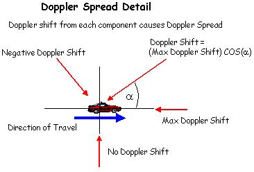
Doppler shift is the frequency shift of the signal due to the relative motion between the transmitter and receiver. The frequency shift is calculated based on the speed of the mobile, the direction of motion and the angle of arrival of the signal. This applies to the direct ray case (no local reflectors).
MIMO technologies hold the promise of higher data rates and increased spectral efficiency by taking advantage of the richness of a multipath environment. Ideally, MIMO systems provide dramatic channel capacity gain through increased spatial diversity. However, this capacity is greatly reduced if the fading characteristic among various channels is correlated.
Spatial Correlation
Traditional methods for modeling wireless channels, such as Power Delay Profile and Doppler spectrum can accurately represent the multipath effects is a single-input, single-output (SISO) system. However, they do not typically include the spatial characteristics that may introduce correlation between the channels of a MIMO system. These spatial effects include: the power azimuth spectrum, antenna position and polarization within the multipath environment, and the gain pattern of the individual antenna elements. As MIMO operation requires low channel-to-channel correlation, it is important to understand how the contribution of each of these spatial characteristics may affect system performance.
Spatial Characteristics
The power azimuth spectrum characterizes the angle spread associated with angles that may be different for the signal paths connecting transmit/receive antenna pairs. Systems operating with a narrow range of angular spread may require antennas physically placed far apart in order to achieve low spatial correlation. In applications where antenna spacing is limited, "cross" polarized antennas coupled with antenna spacing, may help reduce the spatial correlation. Additionally, selecting the antenna pattern of the individual antenna elements, such as omni-directional or directive, can provide an optimal gain pattern for the antenna array depending on the multipath environment.
Refer to the application note, MIMO
Channel Modeling and Emulation Test Challenges, available on the
internet at: www.agilent.com/find/